Pressurizing oil tank of concrete pump

A technology for concrete pump trucks and pressurized fuel tanks, which is applied in the direction of fuel supply tank devices, charging systems, machines/engines, etc. It can solve the problems of reduced fatigue resistance and poor stress on fixed turrets, and achieve structural Simple, improve the oil absorption environment, and improve the effect of cleanliness

Active Publication Date: 2006-05-03
SANY HEAVY IND CO LTD (CN)
View PDF0 Cites 10 Cited by
  • Summary
  • Abstract
  • Description
  • Claims
  • Application Information

AI Technical Summary

Problems solved by technology

In this way, with the increase of the oil suction pipe, the structure of the fixed turret must allow enough space for the oil suction pipe, so that the stress of the fixed turret becomes worse, and the ability to resist fatigue damage is reduced. Therefore, in the limited space of the pump truck How to arrange the oil suction pipe with large diameter has become a difficult problem

Method used


Image

  • Pressurizing oil tank of concrete pump
  • Pressurizing oil tank of concrete pump
  • Pressurizing oil tank of concrete pump

Examples


Embodiment 1

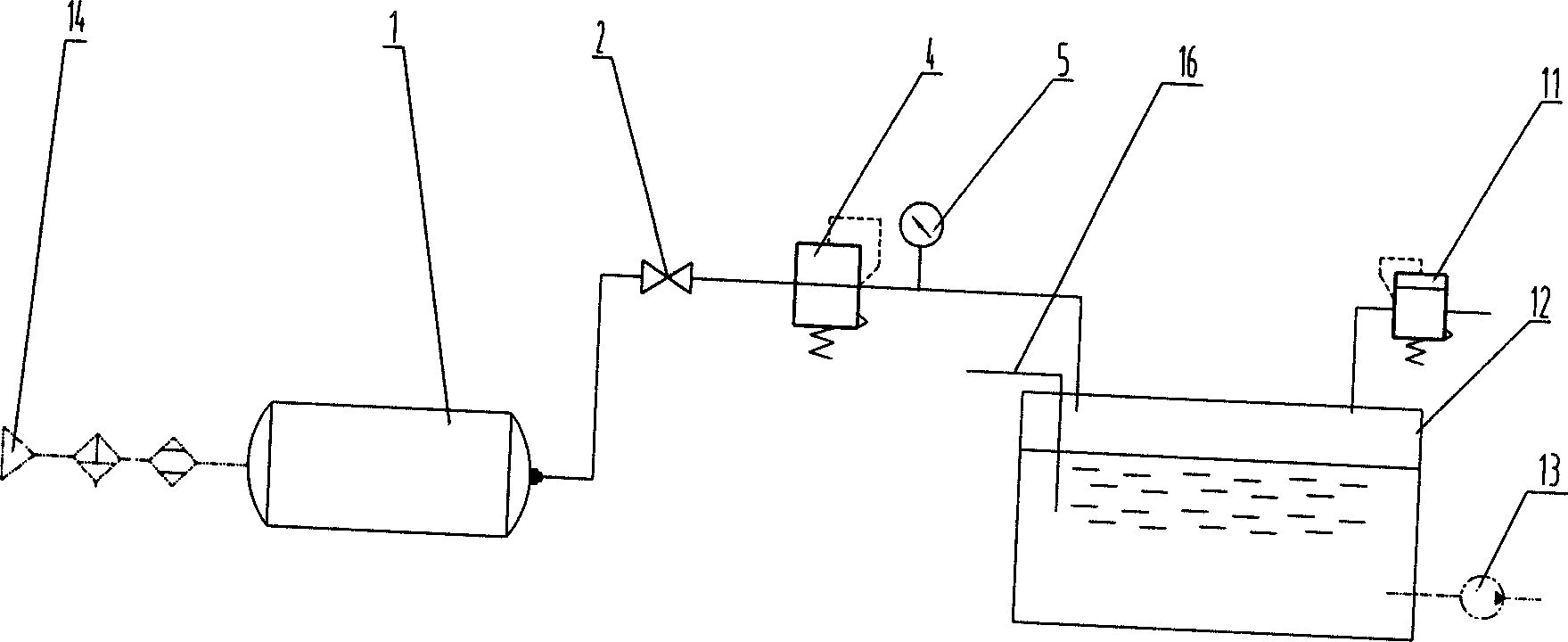
[0029] Embodiment 1: The pressurized oil tank 12 of the concrete pump truck of the present invention is arranged in the fixed turret on the concrete pump truck, and the fixed turret is installed on the auxiliary beam 15 of the pump truck. The fuel tank 12 is fully sealed, and the fuel tank 12 is provided with There are air inlet, oil suction port and oil return port. The oil suction port of the oil tank 12 is connected with the oil pump 13 installed between the beam 15 and the beam 17 of the concrete pump truck through the oil circuit. The safety valve 11 is installed on the oil tank 12. The safety valve 11 It can be used for exhaust when the pressure reducing valve 4 fails or the pipeline is blocked or the air pressure is too high. The air inlet of oil tank 12 links to each other with the air storage tank 1 that is installed on the outside of concrete pump truck chassis frame 17 through air supply device. The gas supply device includes a valve 2, a pressure reducing valve 4 a...

Embodiment 2

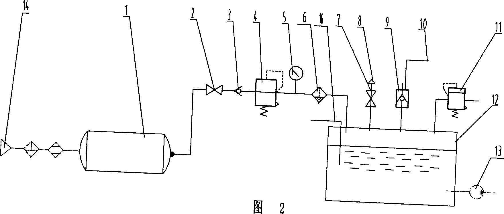
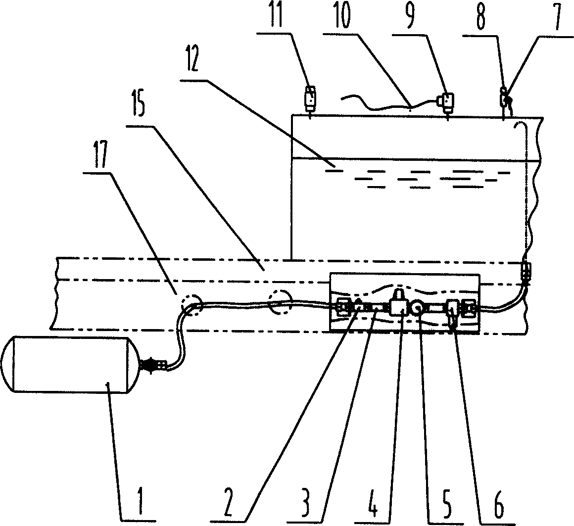
[0031] Embodiment 2: as shown in Figure 2 and image 3 As shown, the pressurized fuel tank 12 of the concrete pump truck of the present invention is arranged in the fixed turret on the concrete pump truck, and the fixed turret is installed on the pump truck beam 15. The fuel tank 12 is fully sealed, and the fuel tank 12 is provided with The air inlet, the oil suction port and the oil return port, the oil suction port of the oil tank 12 is connected with the oil pump 13 installed between the beam 15 and the beam 17 of the concrete pump truck through the oil circuit, and the safety valve 11 is installed on the oil tank 12, and the safety valve 11 can It is used for exhaust when the pressure reducing valve 4 fails or the pipeline is blocked or the air pressure is too high. The air inlet of oil tank 12 links to each other with the air storage tank 1 that is installed on the outside of concrete pump truck chassis frame 17 through air supply device. The air supply device includes a...


PUM


Abstract

The invention discloses a pressure boost sealing oil tank of concrete pump automobile, which is characterized by the following: opening air inlet, oil suction hole and oil return hole on the oil tank; connecting the oil suction hole with the oil pump of concrete pump automobile; connecting the air inlet with the air reservoir through gas supply device. The invention reduces the noise of oil pump and lengthens the lifetime, which optimizes the entire pump automobile structure.

Description

technical field [0001] The invention mainly relates to the field of concrete pump trucks in engineering machinery, in particular to a pressurized fuel tank of a concrete pump truck. Background technique [0002] In the prior art, the concrete pump trucks all use normal-pressure oil tanks. With the continuous increase of the pumping capacity of the pump trucks, the required oil pump displacement is also increasing. In order to ensure the pressure of the oil suction port, the corresponding oil pump The tubes are also getting bigger. Since the oil pump of the pump truck is generally arranged in a narrow area between the chassis girders, in order to reduce the loss along the oil suction pipeline, the domestic pump truck basically uses a fixed turret as a fuel tank at present to ensure that the distance between the fuel tank and the oil pump is relatively short. In this way, with the increase of the oil suction pipe, the structure of the fixed turret must allow enough space for ...

Claims


Application Information

Patent Timeline
IPC IPC(8): F15B1/26
CPCF02M37/14
Inventor 易小刚易秀明王尤毅徐鑫
Owner SANY HEAVY IND CO LTD (CN)
Why Eureka
Try Eureka