Method and apparatus for controlling scanning of mosaic sensor array

一种传感器、控制逻辑电路的技术,应用在控制马赛克式传感器阵列扫描与装置领域,能够解决不能重新配置等问题

Inactive Publication Date: 2006-05-03
GENERAL ELECTRIC CO
View PDF2 Cites 11 Cited by
  • Summary
  • Abstract
  • Description
  • Claims
  • Application Information

AI Technical Summary

Problems solved by technology

However, subelements contain connected cells that cannot be disconnected by switching, and thus cannot be reconfigured

Method used


Image

  • Method and apparatus for controlling scanning of mosaic sensor array
  • Method and apparatus for controlling scanning of mosaic sensor array
  • Method and apparatus for controlling scanning of mosaic sensor array

Examples


Embodiment Construction

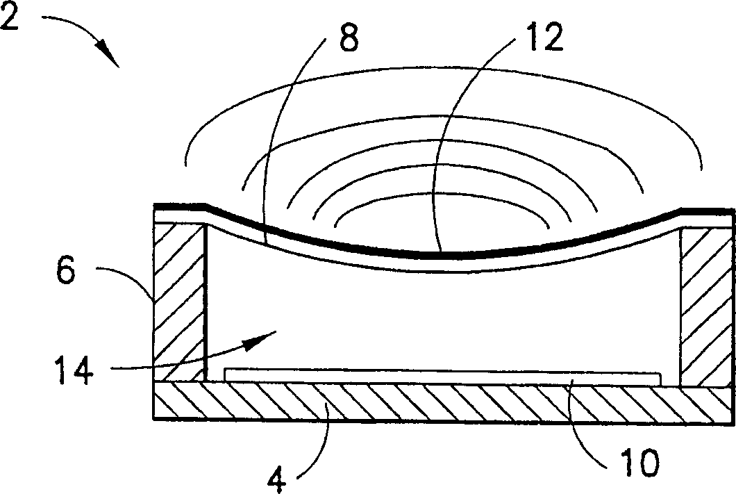
[0055] The present invention is directed to a digital scanning architecture for controlling and configuring a distributed switch matrix. For purposes of illustration, the reconfigurable array will be described with reference to a capacitive micromachined ultrasound transducer (cMUT). However, it should be understood that aspects of the invention disclosed herein are not limited to their use with probes employing cMUTs, but may also be used with probes employing pMUTs, or even cutting piezoelectric arrays, where each cutting subelement is interconnected by Components are connected to the underlying switch layer. The same aspects of the invention can also be used for reconfigurable arrays of optical, thermal or pressure sensors.

[0056] refer to figure 1 , showing a common cMUT transducer unit 2 in cross-section. Such cMUT transducer cell arrays are typically fabricated on a substrate 4, such as a heavily doped silicon (and thus semiconductor) wafer. For each cMUT transduce...


PUM


Abstract

A scanning architecture that makes it possible to update only those ultrasound sensor subelements in a mosaic transducer array that change between views (32). The configuration of the switch matrix is ​​fully programmable. The switch matrix includes: access switches (20) for connecting subelements to the bus; and matrix switches (26) for connecting subelements to subelements. Each sub-element has an associated unit switch unit (50) and addressing and control logic (92, 94, 96), and each unit switch unit includes at least one access switch and at least one matrix switch. Optionally, each unit switch cell also includes a latch (54) for storing future switch states of the switch to be programmed. The switch itself has memory to store its current switch state.

Description

[0001] The US Government has certain rights in this invention under US Government Contract DAMD17-02-1-0181 awarded by the US Army. [0002] This application is a continuation-in-part of US Patent Application 10 / 248968, filed March 6, 2003, and US Patent Application 10 / 383990, from which priority is claimed. technical field [0003] In general, the invention relates to configurable (eg, optical, thermal, pressure, ultrasonic) sensor arrays. In particular, the present invention relates to digital scanning architectures for controlling and configuring configurable sensor arrays. Background technique [0004] Existing ultrasound imaging systems contain arrays of ultrasound transducers that are used to transmit ultrasound beams and then receive reflected beams from the subject of study. Such a scan consists of a sequence of measurements in which focused ultrasound waves are sent and after a short time interval the system switches to a receive pattern where the reflected ultraso...

Claims


Application Information

Patent Timeline
Patent Type & Authority Applications(China)
IPC IPC(8): G01S7/52B06B1/06G01S15/89H03K17/10H03K17/687
CPCA61B8/13B06B1/0292B06B1/0625H03K17/102H03K17/6874H03K17/687
Inventor 罗伯特·G·伍德尼基
Owner GENERAL ELECTRIC CO
Why Eureka
Try Eureka