Magnetic component sensor

A technology of magnetic component sensor and electromagnetic method, which is applied in the field of frequency domain detection to achieve the effects of high sensitivity, strong versatility and small size

Inactive Publication Date: 2006-05-03
JILIN UNIV
View PDF0 Cites 5 Cited by
  • Summary
  • Abstract
  • Description
  • Claims
  • Application Information

AI Technical Summary

Problems solved by technology

[0007] There is no magnetic component detection sensor that can be used for both time domai

Method used


Image

  • Magnetic component sensor
  • Magnetic component sensor
  • Magnetic component sensor

Examples


Embodiment Construction

[0023] Below in conjunction with accompanying drawing and embodiment the present invention will be further described:

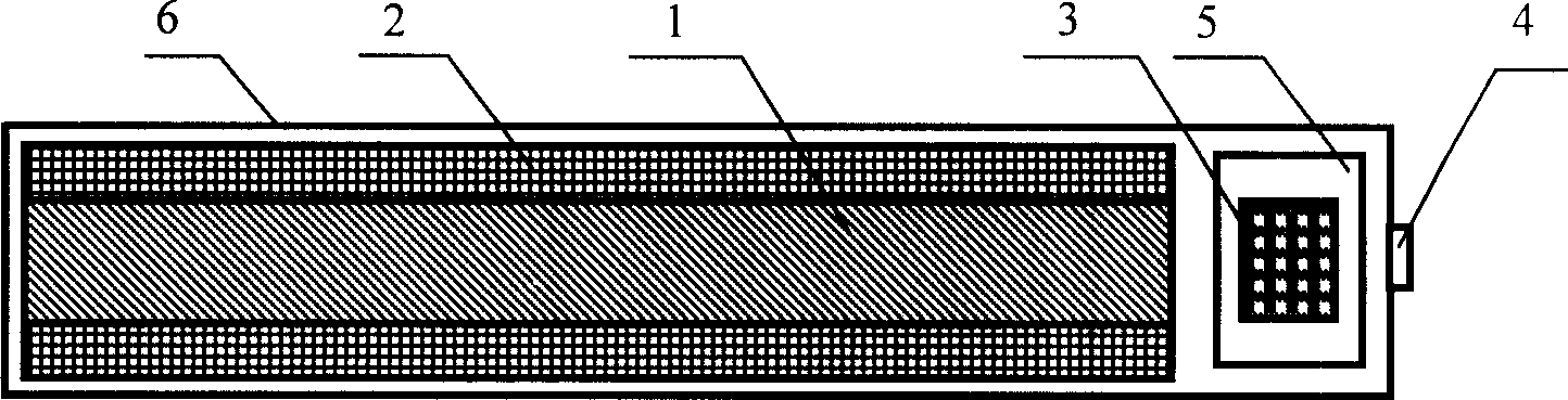
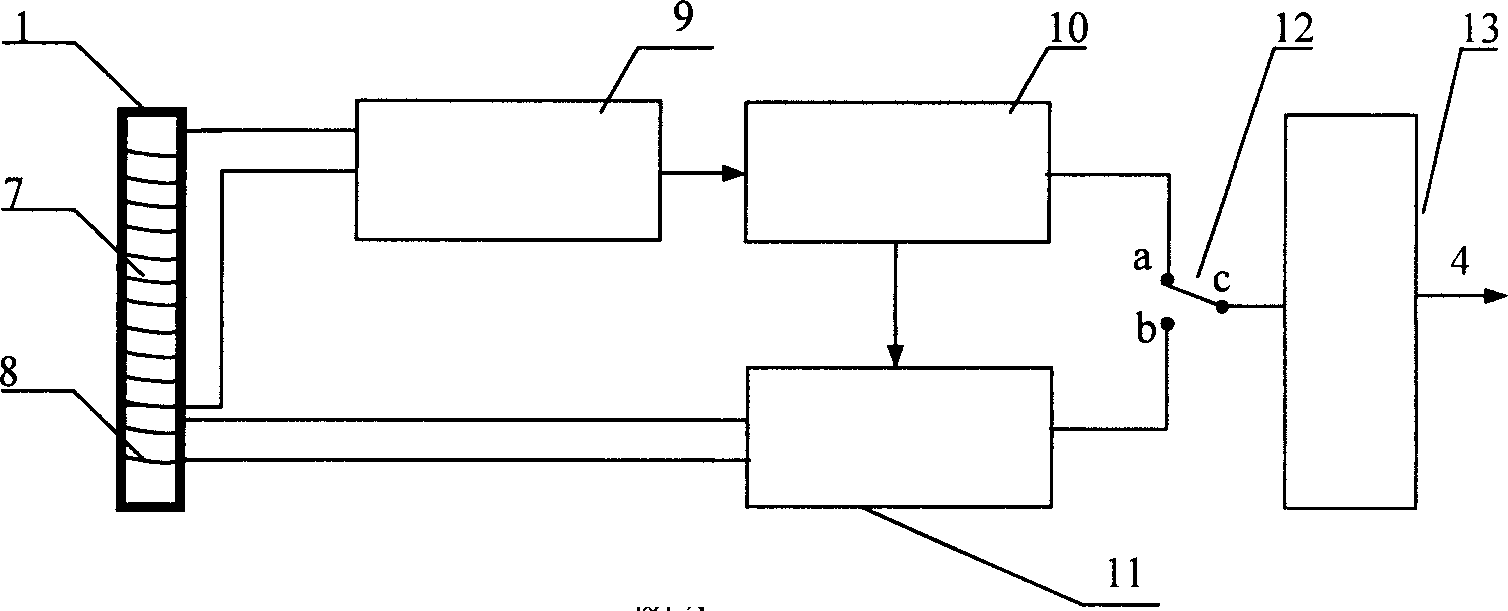
[0024] A coil 2 is wound outside the amorphous alloy magnetic core 1, and the coil 2 is composed of a receiving coil 7 and a feedback compensation coil 8. The coil 2 is connected to the processing compensation circuit 3, and the processing compensation circuit 3 is placed in the processing circuit shielding shell 5 to prevent shielding The electromagnetic influence of the compensation circuit 3 on the coil 2 is dealt with. The output of the sensor is sent out by the signal output joint 4. The elements of the sensor and the processing circuitry are placed in the sensor housing 6 . Processing compensating circuit 3 is to be connected with main amplifying circuit 10 by preamplifying circuit 9; One way of main amplifying circuit 10 is connected with point b of changeover switch 12 through frequency compensating circuit 11; At point a, the output amplifier circu...


PUM


Abstract

The invention discloses a magnetic dividing sensor used in electromagnetic prospecting, which uses Faradayí»s law of electromagnetic as base and adopts amorphous alloy with high magnetic conductivity as magnetic core. When measuring the frequency or the magnetic field, the output of the magnetic dividing sensor is in direct proportion with the frequency during the frequency range of the detecting signal; when measuring the time or the magnetic field, the output of the magnetic dividing sensor is in independence to the frequency during the frequency range of the detecting signal.

Description

Technical field: [0001] The invention relates to a magnetic component sensor used for electromagnetic prospecting, in particular, it can be applicable to both time domain detection and frequency domain detection. Background technique: [0002] Electromagnetic prospecting is an important method in geophysical prospecting methods. In the existing electromagnetic prospecting, due to different detection methods, different magnetic component sensors are used, which are divided into frequency domain detection sensors and time domain detection sensors. The sensors used in electromagnetic prospecting are selected to use frequency domain sensors or time domain sensors according to the prospecting method. [0003] The CLEMP-30K magnetic probe developed by Langfang Institute of Geochemistry and Geochemistry in China has a frequency range of 10Hz-30KHz. The magnetic core is made of high magnetic permeability R5K ferrite magnetic material. Small distributed capacitance increases the sur...

Claims


Application Information

Patent Timeline
IPC IPC(8): G01V3/08G01V3/00G01V3/10
Inventor 王君程德福凌振宝林君
Owner JILIN UNIV
Why Eureka
Try Eureka