Frequency synchronization apparatus and frequency synchronization method

A technology of frequency synchronization and equipment, applied in the direction of synchronization device, synchronization signal speed/phase control, multi-frequency code system, etc., can solve problems such as reducing actual transmission efficiency

Inactive Publication Date: 2006-05-03
PANASONIC CORP
View PDF2 Cites 13 Cited by
  • Summary
  • Abstract
  • Description
  • Claims
  • Application Information

AI Technical Summary

Problems solved by technology

[0012] This correlation technique achieves highly accurate absolute phase correction per subcarrier, but is only applicable to OFDM and leads to the following problem, because two types of synchronization symbols must be sent, so the actual transmission efficiency is reduced

Method used


Image

  • Frequency synchronization apparatus and frequency synchronization method
  • Frequency synchronization apparatus and frequency synchronization method
  • Frequency synchronization apparatus and frequency synchronization method

Examples


no. 1 example

[0063] The frequency synchronization device of the first embodiment is described below with reference to the drawings.

[0064]

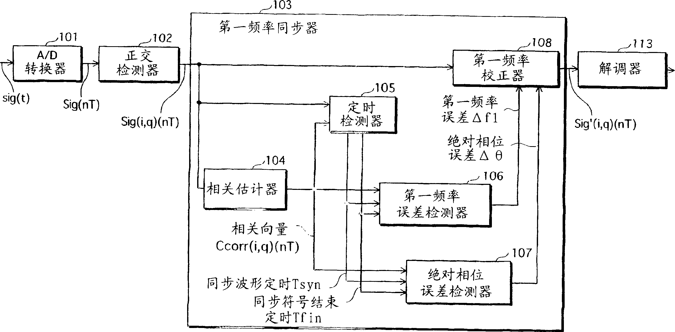
[0065] figure 1 is a functional block diagram showing the overall structure of the frequency synchronization device of the first embodiment together with a part of the wireless receiving device as a higher device. exist figure 1 Among them, the first frequency synchronizer 103 corresponds to the frequency synchronization device, and the A / D (analog / digital) converter 101, the quadrature detector 102 and the demodulator 113 correspond to parts of the wireless receiving device.

[0066] The received signal is converted to an intermediate frequency signal sig(t) suitably selected by a tuner (not illustrated) in the wireless receiving device. The A / D converter 101 converts the signal sig(t) into a time-series digital signal Sig(nT), and the quadrature detector 102 obtains the baseband quadrature component signal Sig(nT) by performing quadrature dete...

no. 2 example

[0121] The frequency synchronization device of the second embodiment is different from the frequency synchronization device of the first embodiment, because the frequency synchronization device of the second embodiment adds a holder for holding the first frequency error Δf1 and the absolute phase error Δθ, and The received signal is corrected in accordance with the first frequency error Δf1 and the absolute phase error Δθ held by the holder.

[0122] The frequency synchronization device of the second embodiment is described below with reference to the drawings. Note that the same structural elements as those in the first embodiment are therefore given the same reference numerals and are omitted from the following description.

[0123] Figure 10 is a functional block diagram showing the overall configuration of the frequency synchronization device of the second embodiment together with a part of the wireless receiving device as a higher device. exist Figure 10 Among them, ...

no. 3 example

[0134] The frequency synchronization device of the third embodiment differs from that of the second embodiment in that it additionally includes a second frequency synchronizer for performing frequency synchronization according to a modulation method. The second frequency synchronizer corrects a frequency error of the received signal, for example, by demodulating the received signal to find a time sequence of information symbols, and detecting a shift amount of a symbol point of each or a plurality of symbols.

[0135] The frequency synchronization device of the third embodiment is described below with reference to the drawings. Note that the same structural elements as those in the second embodiment are therefore given the same reference numerals and are omitted from the following description.

[0136] Figure 11 is a functional block diagram showing the overall structure of the frequency synchronization device of the third embodiment together with part of the wireless receiv...


PUM


Abstract

The first frequency synchronization means (103) corresponds to the frequency synchronization device of the present invention. A higher device, eg a wireless receiver, provides a received signal to the first frequency synchronization means (103) via an A / D converter (101) and a quadrature detector (102). A sync symbol including a predetermined waveform at least twice is incorporated into the received signal. A correlation estimator (104) generates a reference signal representing the same waveform as the synchronization symbol, and sequentially finds a correlation vector between the received signal and the reference signal. The first signal error detector (106) finds the frequency error from the average phase difference of the predetermined correlation vectors, and finds the absolute phase error from the transition of the absolute phase of the predetermined correlation vectors. A first frequency corrector (108) simultaneously imparts a frequency shift and a phase rotation for canceling errors to the received signal.

Description

technical field [0001] The present invention relates to a frequency synchronization device and a frequency synchronization method, and more particularly to a technique for simultaneously correcting frequency shift and absolute phase in a received signal based on a single synchronization symbol. Background technique [0002] In recent years many transmission methods have been developed for mobile communications, digital CATV (Cable TV) systems, and the like. In order to perform the transmission correctly, it is necessary for the receiving device to establish synchronization between the frequency of the received signal and the internal received reference signal. This is because if the receiving device demodulates the received signal without establishing synchronization, the receiving device will not be able to correctly obtain the original transmitted data. [0003] Frequency synchronization is typically performed using synchronization symbols, which are signaled in conjuncti...

Claims


Application Information

Patent Timeline
Patent Type & Authority Applications(China)
IPC IPC(8): H04L7/04H04L7/10H04L27/00H04L27/26
CPCH04L27/0014H04L7/042H04L7/043H04L27/2657H04L2027/003H04L2027/0065H04L2027/0067
Inventor 尾本幸宏白方亨宗浦部嘉夫原田泰男
Owner PANASONIC CORP
Why Eureka
Try Eureka