Air conditioner

A technology for air conditioners and pressure reducers, which can be applied to compressors with reversible cycles, household refrigeration devices, defrosting, etc., can solve the problems of condensation on refrigerant heaters, increased heater volume, and increased pressure loss. , to achieve the effect of small change of compressor oil, improved operation reliability and small pressure change

Inactive Publication Date: 2006-05-10
PANASONIC CORP
View PDF1 Cites 9 Cited by
  • Summary
  • Abstract
  • Description
  • Claims
  • Application Information

AI Technical Summary

Problems solved by technology

[0016] In addition, at the above-mentioned refrigerant confluence, the amount of refrigerant circulation will increase, and the pressure loss will also increase
As a solution, it is necessary to increase the diameter of the piping, but this will cause a problem that the volume of the heater will increase
[0017] In addition, when the refrigeration circuit is in operation, the inside of the pipeline in the refrigerant heater 104 is full of low-pressure refrigerant, and the temperature of the refrigerant heater 104 is usually very low, so it is easy to generate knots on the refrigerant heater 104. dew
In addition, when the two-way valve 108 fails and the refrigerant leaks, dew condensation is also likely to occur in the refrigerant heater.
In this way, especially when the refrigerant heater adopts a heat conduction heater, etc., there are great problems in the reliability and safety of the refrigerant heater.

Method used


Image

  • Air conditioner
  • Air conditioner
  • Air conditioner

Examples


Embodiment 1

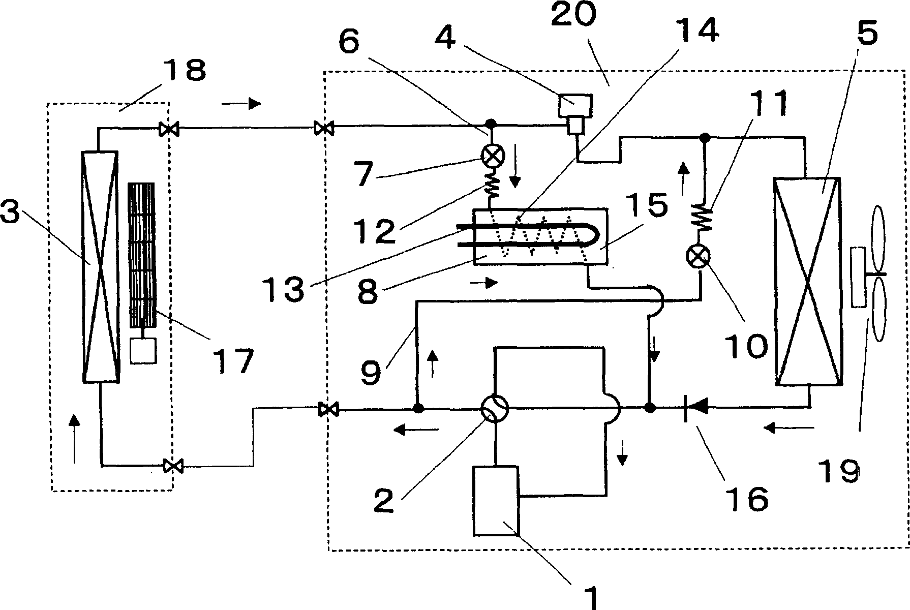
[0043] figure 1 It is a structural diagram of the air conditioner in the present invention. exist figure 1 Among them, the outdoor unit 20 is equipped with: a compressor 1, a four-way valve 2, a pressure reducer 4, an outdoor heat exchanger 5, a first bypass circuit 6, a two-way valve for refrigerant heating 7, and a refrigerant heater 8. The second bypass circuit 9, the two-way valve 10 for defrosting, the two-way valve 11 of the second bypass circuit, the two-way valve 12 of the first bypass circuit, the refrigerant heating device 13, and the refrigerant passing pipe 14 , heat storage unit 15, check valve 16 and outdoor fan 19. The indoor unit 18 is provided with an indoor heat exchanger 3 and an indoor fan 17 . The pressure reducer 4 here may be an electromagnetic expansion valve.

[0044] Figure 4 Shown in the control system block diagram of embodiment 1 of the present invention, Figure 5 The working sequence diagram for the operation of the control system. Fig...

Embodiment 2

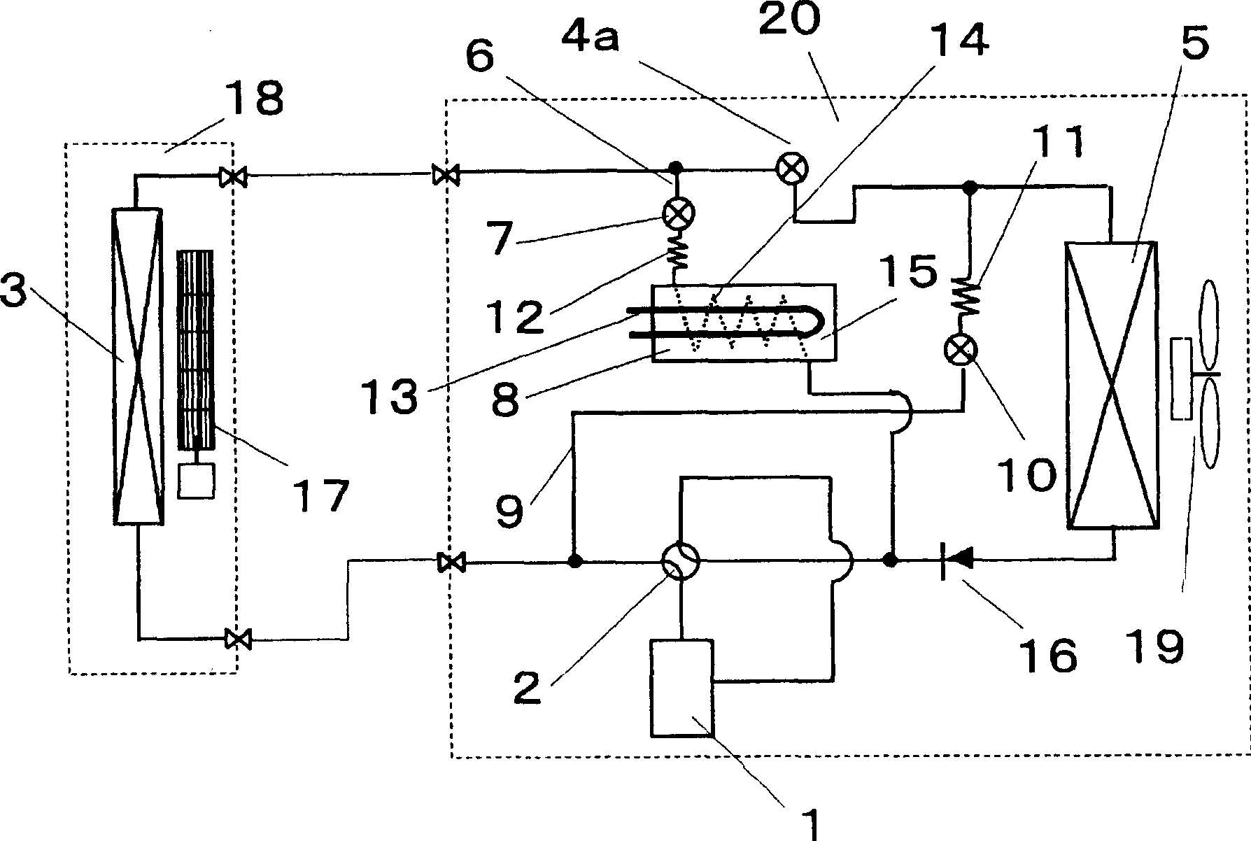
[0055] Next, pass figure 2 Embodiment 2 of the present invention will be described.

[0056] The difference between the present embodiment and the first embodiment is that the decompressor 4 is constituted by using a two-way valve 4 a that does not have a depressurization function but only performs opening and closing operations of the refrigerant. In such a case, defrosting may be performed while continuing heating.

[0057] The operation of the two-way valve 4a is as follows. At the same time as the two-way valve 7 for refrigerant heating is controlled to be opened or a little later, the two-way valve 4a is controlled to be closed.

Embodiment 3

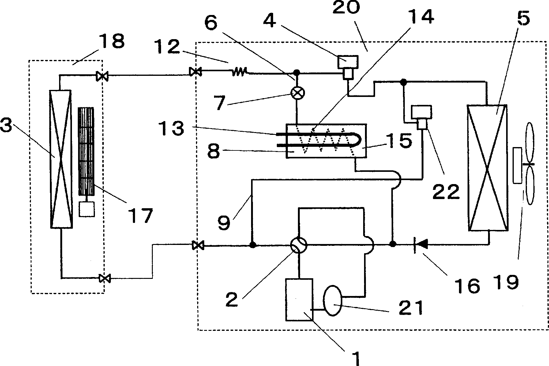
[0059] pass below image 3 Embodiment 3 will be described.

[0060] The difference between this embodiment and Embodiment 1 is that there is no pressure reducer between the two-way valve 7 for heating the refrigerant and the heater 8, but a pressure reducer between the indoor heat exchanger 3 and the pressure reducer 4 Reducer 12.

[0061] With such an arrangement, the first bypass circuit 6 can be simplified, thereby reducing the volume of the body and reducing the manufacturing cost.

[0062] In addition, a gas-liquid separator 21 is provided on the suction side of the compressor 1 .

[0063] Due to the different specifications of the compressors 1 , some compressors 1 have a weaker tolerance to liquid return. In such a case, it is necessary to provide such a gas-liquid separator 21 .

[0064] In particular, liquid return is more during defrosting operation, so the impact of liquid return on compressor reliability needs to be considered.

[0065] In addition, if the pre...


PUM


Abstract

PROBLEM TO BE SOLVED: To provide an air conditioner for performing a defrosting operation by continuing a heating operation.

SOLUTION: A first by-pass circuit 6 for connecting the suction side of a compressor 1 with a part between an indoor heat exchanger 3 and a decompression apparatus 4 of a heat pump type refrigerating cycle is disposed, and a two-way valve 7 and a refrigerant heater 8 are disposed in the first by-pass circuit 6. A second by-pass circuit 9 for connecting a part between the decompression apparatus 4 and an outdoor heat exchanger 5 to a part between a four-way valve 2 and the indoor heat exchanger 3 connected to the refrigerating cycle is provided, and a two-way valve 10 is disposed in the second by-pass circuit 9. When the outdoor heat exchanger 5 is defrosted, the two-way valve 7 of the first by-pass circuit 6 and the two-way valve 10 of the second by-pass circuit 9 are opened to perform the heating and defrosting operations.

COPYRIGHT: (C)2006,JPO&NCIPI

Description

technical field [0001] The present invention relates to an air conditioner capable of defrosting frost adhering to an outdoor heat exchanger while continuing the heating operation when the heating operation is performed by a heat pump. Background technique [0002] At present, the defrosting method in the heat pump air conditioner generally adopts a defrosting method in which the four-way valve is switched to reverse the flow of the refrigerant in the refrigerating circuit. [0003] That is, the refrigerant flow direction during the defrosting operation is the same as that during cooling, and the high-temperature and high-pressure refrigerant flows in the outdoor heat exchanger, thereby melting the frost attached to the heat exchanger. [0004] However, in such a defrosting method, since the heat exchanger on the indoor side becomes an evaporator during defrosting, there is a problem that the indoor temperature drops and the user suddenly feels chilly. [0005] As a solutio...

Claims


Application Information

Patent Timeline
Patent Type & Authority Applications(China)
IPC IPC(8): F25B47/02F24FF25B13/00
CPCF25B47/022F25D21/06
Inventor 西原义和佐藤新一内山邦泰
Owner PANASONIC CORP
Why Eureka
Try Eureka