Magnetic storage device

A magnetic storage and storage area technology, applied in the direction of information storage, static memory, digital memory information, etc., to achieve the effect of simple structure, reduced write current, small size and structure

Inactive Publication Date: 2006-05-10
TDK CORPARATION
View PDF2 Cites 2 Cited by
  • Summary
  • Abstract
  • Description
  • Claims
  • Application Information

AI Technical Summary

Problems solved by technology

[0004] However, in conventional magnetic storage devices, in order to further reduce the write current, it is necessary to increase the magnetic flux concentrated on the magnetoresistive element by increasing the size of the yoke, etc. The reduction of the input current has reached the limit

Method used


Image

  • Magnetic storage device
  • Magnetic storage device
  • Magnetic storage device

Examples


Embodiment 1

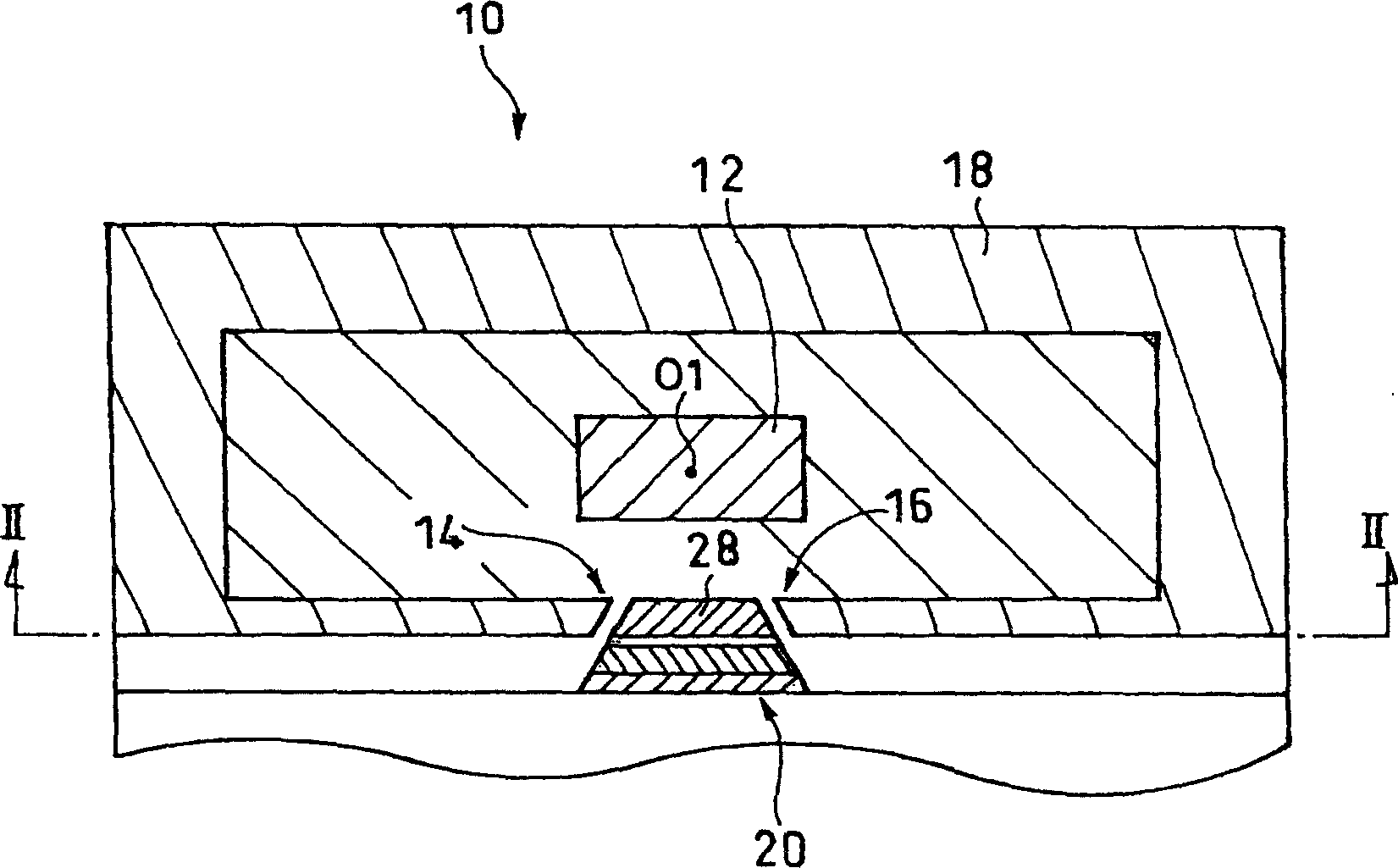
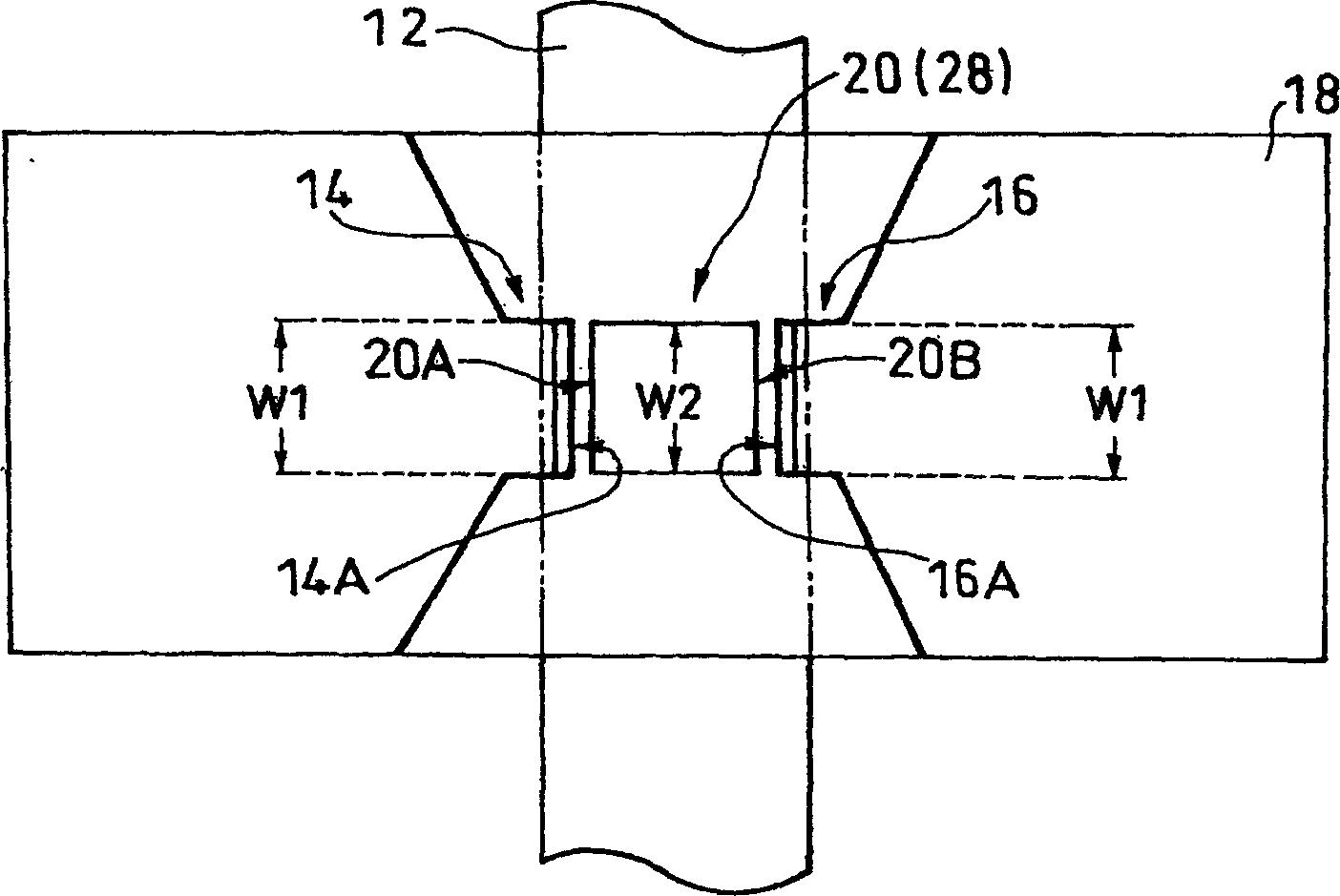
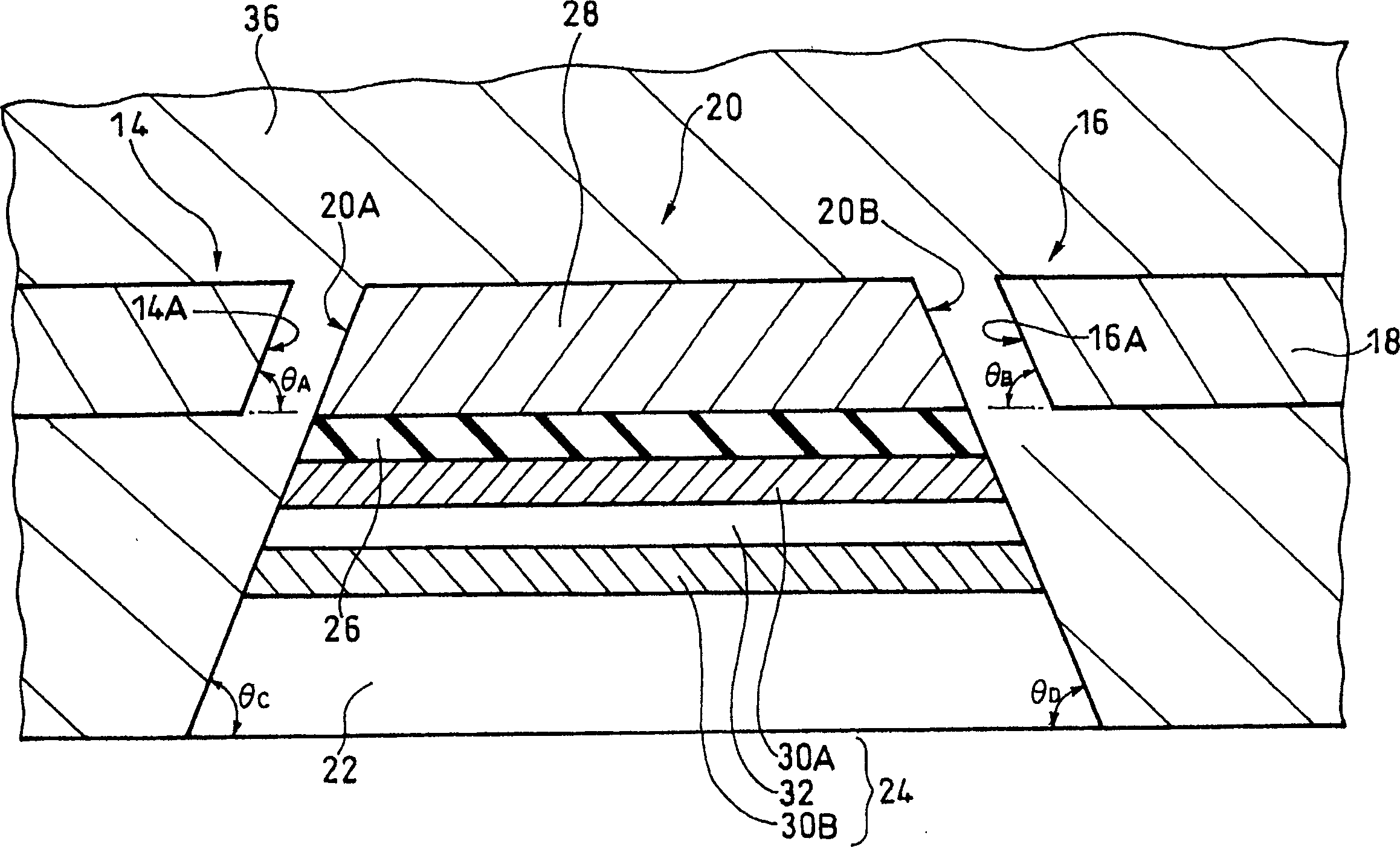
[0031] The magnetic storage device 10 according to Embodiment 1 of the present invention has a plurality of storage areas, and in each of the plurality of storage areas, such as figure 1 and figure 2 As shown, it includes: wiring 12 for providing an external magnetic field by writing current; a substantially annular yoke 18 having a pair of open ends 14 and 16 facing each other across a gap; Magnetization direction of the second magnetic layer (magnetic sensitive layer) 28 of the magnetoresistance effect element 20 .

[0032] The yoke 18 is disposed so as to surround the outer periphery of the wiring 12 in a part in the extending direction of the wiring 12 . Since the wiring 12 is for writing magnetization information on the magnetoresistance effect element 20 , it is arranged so as to pass through the vicinity of the axis O1 of the yoke 18 in the first embodiment.

[0033] In addition, the yoke 18 is made of ferromagnetic iron-nickel alloy (NiFe) in the first embodiment, a...


PUM


Abstract

A magnetic storage device (10), comprising a magnetoresistance effect element (20), the magnetoresistance effect element (20) is opened with at least a part of a pair of side surfaces (20A, 20B) and a yoke (18) The end surfaces (14A, 16B) of the end portions (14, 16) are arranged in a manner facing each other, and a pair of side surfaces (20A, 20B) of the magnetoresistance effect element (20) and a pair of yoke (18) are open. Each end surface (14A, 16B) of the end portion (14, 16) has a predetermined angle, and the write current can be reduced while having a small and simple structure.

Description

technical field [0001] The invention relates to a magnetic storage device capable of storing information by utilizing the magnetoresistance effect. Background technique [0002] In recent years, a magnetic storage device called a Magnetic Random Access Memory (MRAM: Magnetic Random Access Memory) capable of storing information using a magnetoresistive effect has been widely known as a nonvolatile memory device capable of high-speed operation. [0003] In such a magnetic storage device, in order to increase the operating speed and reduce the write current, etc., it is required to efficiently write to the magnetoresistance effect element. For example, it has been proposed to concentrate the magnetic flux of the magnetic field generated around the wiring on the magnetic Proposal of a magnetic storage device with a substantially annular yoke of a resistive element (refer to JP-A-2000-90658 and JP-A-2004-128430). [0004] However, in conventional magnetic storage devices, in ord...

Claims


Application Information

Patent Timeline
Patent Type & Authority Applications(China)
IPC IPC(8): G11C11/15H01L43/08
CPCG11C11/16
Inventor 原谷进
Owner TDK CORPARATION
Why Eureka
Try Eureka