
Method for manufacturing plasma display device

A technology of a plasma display and a manufacturing method, which are applied in the manufacture of discharge tubes/lamps, cold cathode manufacture, electrode system manufacture, etc., can solve the problems of waste of manufacturing engineering cost and complicated engineering, and achieve saving engineering cost and simple manufacturing process. The effect of reducing the number of manufacturing processes

Inactive Publication Date: 2006-05-10
NANJING LG TONGCHUANG COLOR DISPLAYS SYST CO LTD
View PDF0 Cites 0 Cited by
  • Summary
  • Abstract
  • Description
  • Claims
  • Application Information

AI Technical Summary

Problems solved by technology

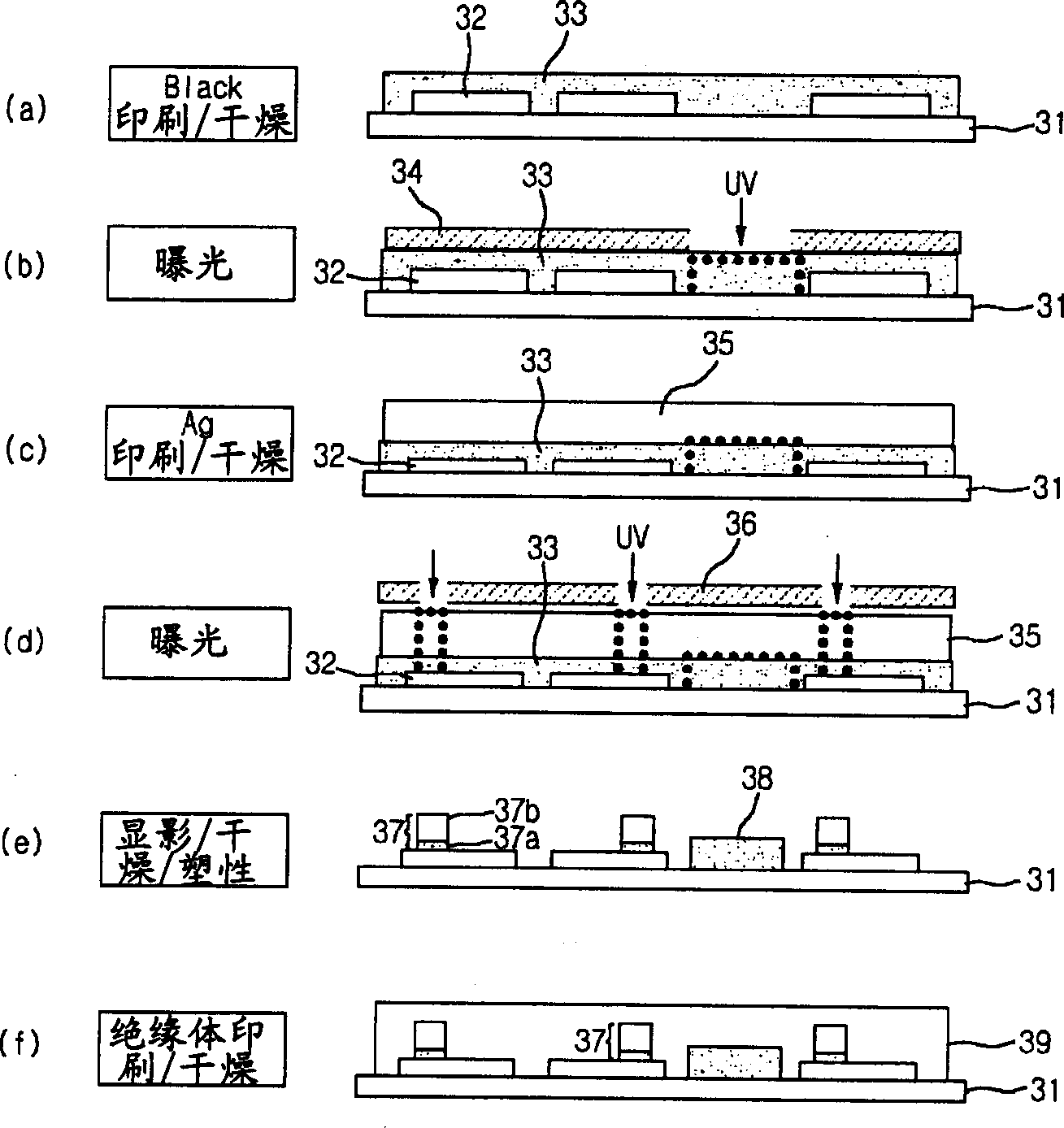
In the existing method of manufacturing the upper substrate of a plasma display, when forming the metal bus electrodes, the process of printing and drying the black electrode paste and the silver electrode paste process and the exposure process need to be carried out twice respectively, which complicates the entire process
Moreover, there is a problem of wasted manufacturing engineering cost due to this

Method used


Image

  • Method for manufacturing plasma display device
  • Method for manufacturing plasma display device
  • Method for manufacturing plasma display device

Examples


Embodiment Construction

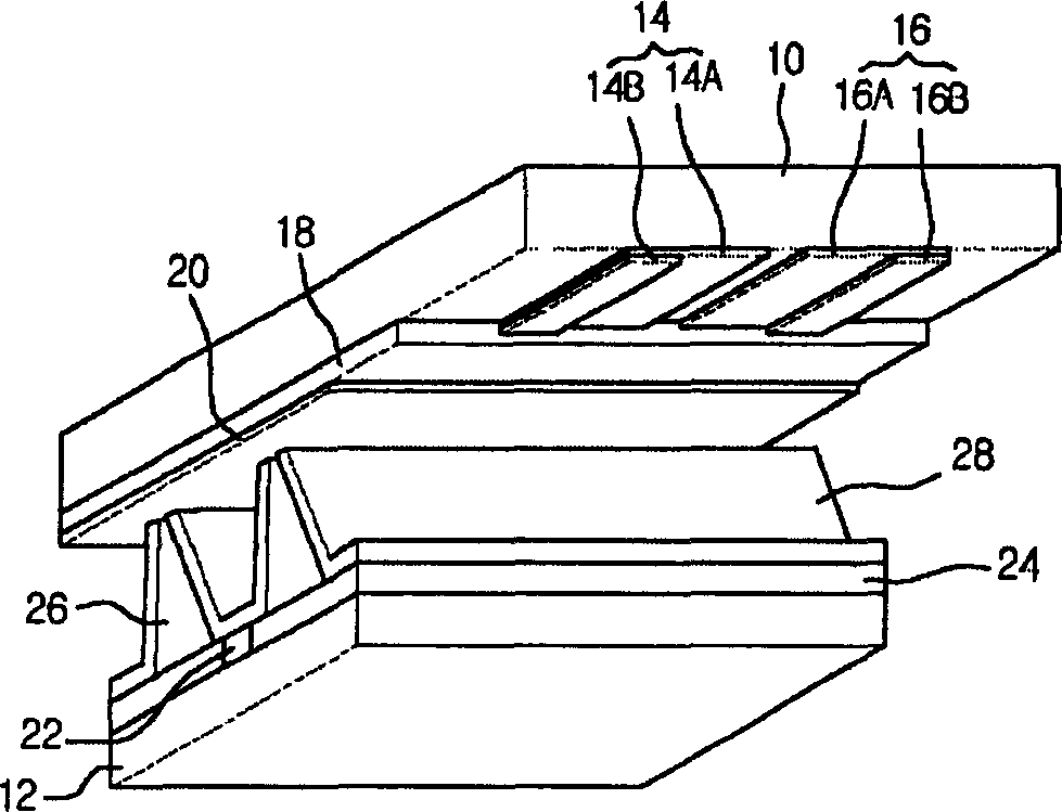
[0028] Hereinafter, embodiments of the plasma display and its manufacturing method of the present invention will be described in detail with reference to the accompanying drawings.

[0029] The plasma display of the present invention is composed of the following parts, and is characterized in this way: a plurality of first sustain electrode groups formed on the first transparent electrode and the first metal electrode formed on the upper substrate; The distance between the second transparent electrode and the second metal electrode formed in parallel is a plurality of second sustain electrode groups; it is at right angles to the first and second sustain electrode groups, crossing, and a plurality of address electrodes formed on the lower substrate; In order to isolate the upper substrate and the lower substrate, a plurality of partition walls are formed on the lower substrate in parallel with the address electrodes.

[0030] The above-mentioned first and second metal electrode...


PUM

PropertyMeasurementUnit
Thicknessaaaaaaaaaa

Abstract

This invention relates to one plasma display process method to simplify the process, which comprises the following steps: Pressing the pre-made green light band on the upper base board with transparent electrode; sustainable exposing by ultraviolet with different wavelengths; developing the exposed green light band and drying and shaping to form metal electrodes. So, this invention can reduce process to save cost.

Description

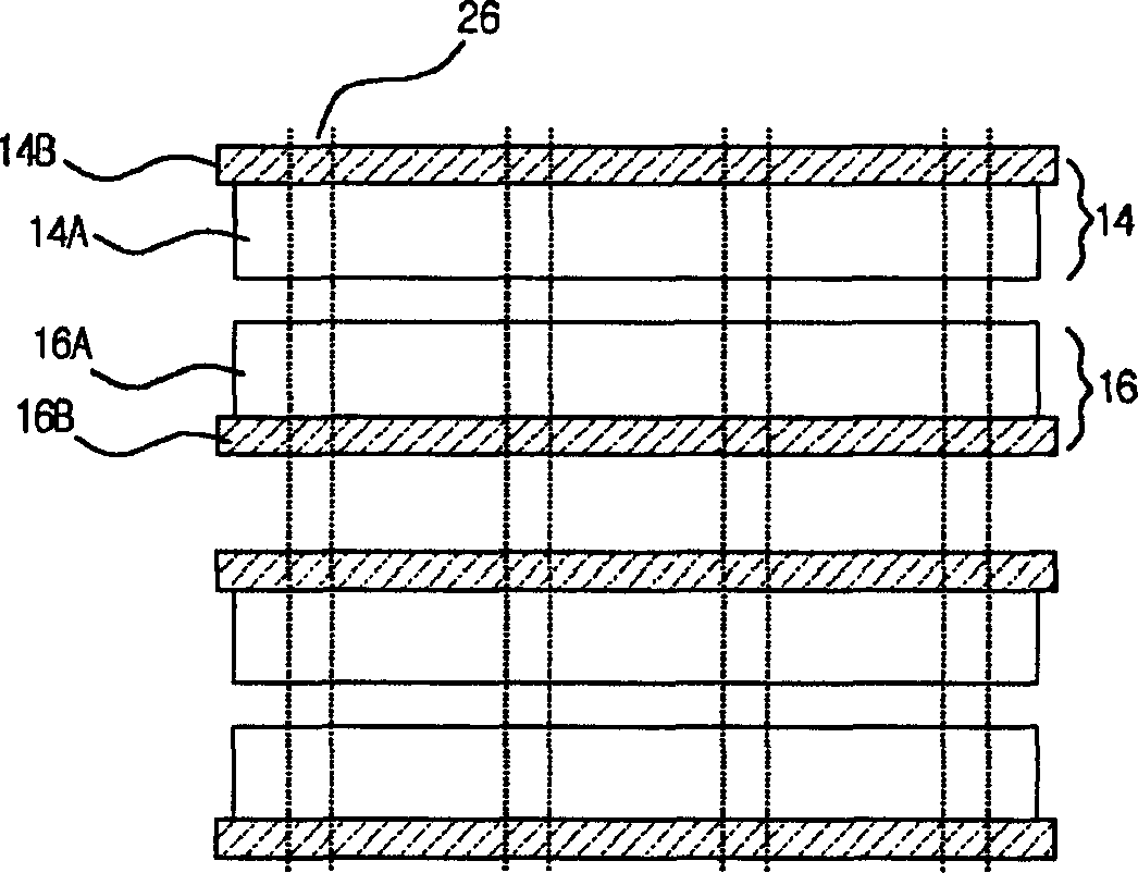
【Technical field】 [0001] The present invention relates to a plasma display, in particular to a method for manufacturing a plasma display capable of simplifying the manufacturing process. 【Background technique】 [0002] Recently, a plasma display (Plasma Display Panel: hereinafter abbreviated as 'PDP'), a flat panel display device that is easy to manufacture and has the advantage of a large display screen, has attracted attention. Plasma displays usually display images by adjusting each discharge period based on digital video data. The most representative of this kind of plasma display is figure 1 Among them, there are 3 electrodes and AC plasma displays driven by AC voltage. [0003] figure 1 It is a perspective view of the unit structure arranged in a matrix in a common AC plasma display. figure 2 It is a schematic diagram of the upper substrate electrode arrangement structure of an AC plasma display. [0004] refer to figure 1 and figure 2 , we can see that the un...

Claims


Application Information

Patent Timeline
IPC IPC(8): H01J9/02
Inventor 金济奭柳镇馨
Owner NANJING LG TONGCHUANG COLOR DISPLAYS SYST CO LTD
Learn More