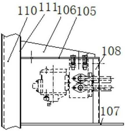
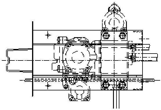
[0005] But this mounting seat has the following problems: when the side
wall plate 11 and the
bolster 110 connected to the mounting seat plate 107 are severely corroded and need to be repaired and replaced by the factory, the valve mounting seat 105 must also be
cut off and the valve mounting seat 105 mother will be
cut during the removal process. When assembling, it is necessary to add a new valve mounting seat 105, which affects the maintenance cost and maintenance efficiency; the valve mounting seat 105 is assembled and welded by various specifications of plates and section steel, and the
welding workload is large, causing great environmental
pollution; the valve Mounting seat 105
assembly welding needs to involve multiple manufacturing processes such as blanking, drilling, and
assembly welding. There are cumbersome
raw material procurement and access to parts, time-consuming and laborious, long manufacturing cycle, low production efficiency, and difficult
quality assurance and manufacturing. Or problems such as high maintenance costs
However, during operation, due to factors such as low manufacturing and maintenance quality or poor
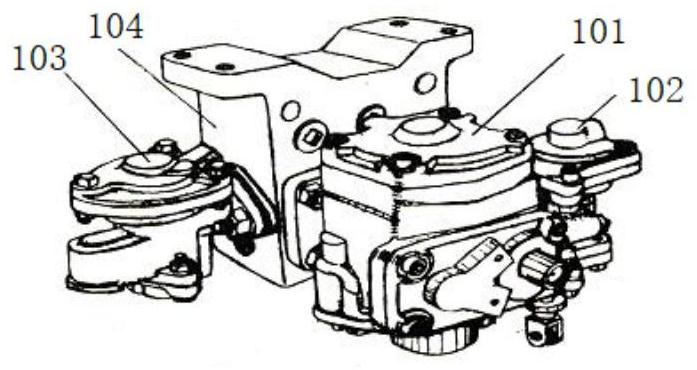
operating environment, the 120-type control valve may have temporary failures, and the
cut-off plug door of the vehicle needs to be closed, commonly known as the closing car. The grouping of the closing car in the
train is clearly It is stipulated that the vehicle operation department must first dismantle the protective device when the
train fleet handles the closed car
Because the transportation organization of the railway bureau is often relatively tight, if the closed car is picked up and sent to the
station for temporary repairs, the
train shunting personnel at the
station are required to perform the car dumping operation, which will also affect the train’s punctual departure due to the car dumping operation, especially when it is concentrated to the departure point. In some cases, it is more difficult to dump the car, and the contradiction between the needs of operation and maintenance and transportation organization is more prominent
In the case of both transportation organization and operation maintenance, the only option is to repair the closed-door car in the train fleet; the efficiency of repairing the closed-door car with a brake failure in the train fleet is low, and the damage to the protective cover 109 cannot be recovered. Because the protective cover 109 has a special structure, After the bolts and nuts are spot welded, they cannot be disassembled on site. It is difficult to saw the bolts with a saw blade. At present, most of the vehicle operating systems choose to use the bow saw intermediate to connect the anti-theft cover steel plate of the
branch pipe, and separate the brake valve from the protective cover 109. carry out replacement repair
This method is labor-intensive and inefficient, and it is difficult to complete within the technical
inspection time. At the same time, after using this method to deal with the closed car, the protective cover has been "destructively" processed. In the train team, the anti-theft cover cannot be restored to its original state. Simple binding with iron wire, if the binding is not firm, there is still a hidden danger that the protective cover 109 will fall off during the operation of the vehicle; in addition, the
cutting part will need to be repaired by welding when performing section repairs or factory repairs in the future, resulting in greater waste
[0009] The design of the suspension-mounted protective cover 109 for the 120-type control valve of the existing railway hopper car does not fully consider the needs of train inspection site maintenance, especially the
spot welding of mounting bolts and nuts. Only the functions of preventing
loss and damage are considered, and the vehicle is not considered According to the needs of the train fleet of the
system, although the relevant regulations can detain the closed car with a protective cover 109 into the
station repair site for
processing, but often due to the needs of the transportation organization, in most cases, it needs to be processed in the train fleet, even if it is buckled The way to deal with inbound repair work is also
oxygen cutting installation bolts and nuts, which is also destructive disassembly; at present, the tools used for
processing the protective cover 109 in the vehicle operation
system are mainly saw bows, because the bolts and nut steel at the
spot welding parts The material changes, the
hardness is higher, and it is more difficult to
handle the saw bow. If
oxygen cutting is used, there will be a greater safety
hazard in on-site pick-up and handling; if pneumatic cutting or electric cutting is used, it is also inconvenient to carry. Restricted by factors such as space and sparks during
processing, there are certain potential safety hazards. The mismatch of on-site maintenance tools increases the difficulty of processing, and to a certain extent also restricts the enthusiasm for on-site processing of closed-door vehicles, which is not conducive to the improvement of the overall operating quality of vehicles.
[0010] The existing railway hopper car 120 type control valve suspension installation protective cover also has the following problems: the protective cover 109 has many components and mounting bolts, and the
assembly and disassembly are time-consuming and laborious, which affects the assembly efficiency and quality, poor reliability, and high manufacturing and maintenance costs , the overall economic benefit is relatively poor; when disassembling the protective cover 109 needs to cut bolts or rivets, it is easy to
burn out the mounting holes, causing the protective cover 109 to need to be welded to process holes or scrapped; the existing protective cover 109 is not well sealed, which easily causes the valve to be damaged. Rainwater
erosion and
corrosion will affect the life of the valve and cause failures; the protective cover 109 adopts the structure of steel plate assembly welding, which requires a lot of welding in use and pollutes the environment; the installation bolts of the protective cover 109 near the side wall are relatively close to the side wall panels, resulting in a narrow space , the space for
wrench movement is limited, and it is time-consuming and laborious to fasten the bolts or urgently need to be disassembled in case of emergency failure, and
spot welding is also difficult after the bolts and nuts are tightened; the existing 120-type control valve consists of emergency valve or main valve or semi-automatic When any failure of the
relief valve occurs, the protective cover 109 needs to be disassembled as a whole before maintenance. Due to the large number of fasteners, it takes a lot of time to disassemble and reassemble after maintenance.
[0011] The existing 120-type control valve suspension mounting seat and protective cover device have a
high probability of welding defects due to many welds, and welding defects will directly affect the strength of the valve mounting seat 105 and the normal protection of the protective cover 109, which may cause traffic safety. ACCIDENT
[0012] With the rapid development of my country's railway hopper cars and the improvement of the overall design and manufacturing level of vehicles, traditional mounting seats and protective devices can no longer meet the requirements of anti-theft, anti-smashing, anti-damage, convenient disassembly and installation, and commercialization.

