
Cutting device for thin metallic plate

A cutting device, metal technology, applied in the direction of shearing device, shearing machine accessory device, pipe shearing device, etc., can solve the problems of damaged tools, large burrs, etc., and achieve the effect of reducing the occurrence of burrs

Inactive Publication Date: 2006-05-10
HONDA MOTOR CO LTD
View PDF0 Cites 7 Cited by
  • Summary
  • Abstract
  • Description
  • Claims
  • Application Information

AI Technical Summary

Problems solved by technology

However, at this time, although no burrs are generated at the corners (corner edges) on the inner peripheral side of the above-mentioned metal ring, relatively large burrs are generated at the corners on the outer peripheral side. Disadvantages of plastic treatment
Moreover, it is well known that when the inner and outer sides of the drum are cut by the contact of the shearing blades, no burrs will be generated at the corners of the inner and outer peripheral sides, but there is a concern that the two blades will be damaged by contact after cutting the drum. knives

Method used


Image

  • Cutting device for thin metallic plate
  • Cutting device for thin metallic plate
  • Cutting device for thin metallic plate

Examples


Embodiment Construction

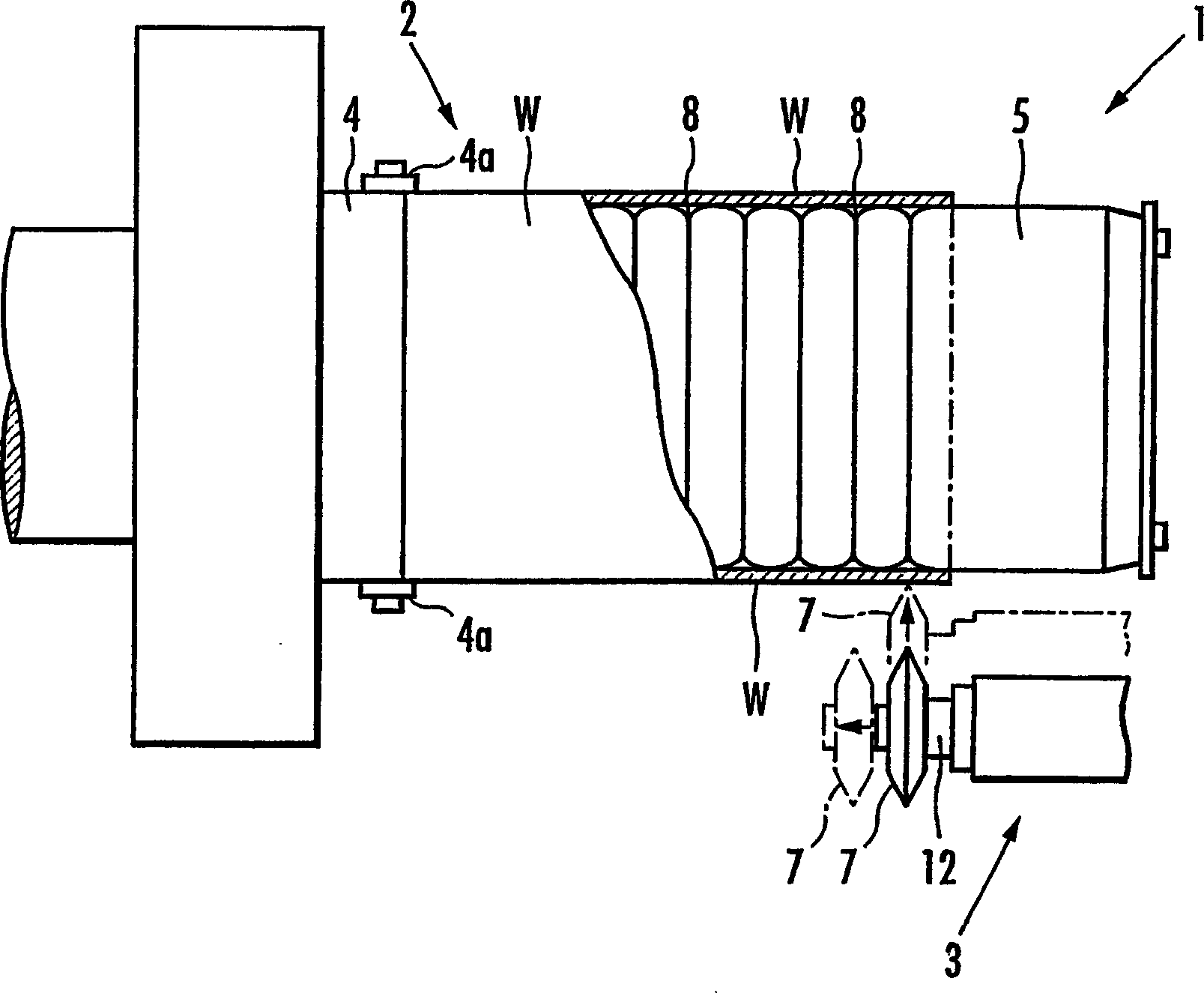
[0037] figure 1 The cutting device 1 according to the present embodiment is a metal ring for manufacturing a continuously variable transmission belt (not shown) by cutting a metal drum W in a ring-cut shape at a predetermined width. The above-mentioned drum W is formed by forming a rectangular flat thin plate of ultra-high strength steel into a cylindrical shape, and then joining both end edges by butt welding.

[0038] The cutting device 1 of the present embodiment, as figure 1 As shown, it is composed of a roll supporting mechanism 2 that supports the above-mentioned roll W, and a cutting mechanism 3 that cuts the roll W.

[0039] The above-mentioned roller supporting mechanism 2 is provided with: a supporting shaft 4, which is rotated by a rotation drive mechanism not shown in the figure; Contact tools for internal contact.

[0040] The above-mentioned support tool 5, such as figure 1 As shown, metal is formed into a cylindrical shape, and a plurality of grooves 8 are f...


PUM


Abstract

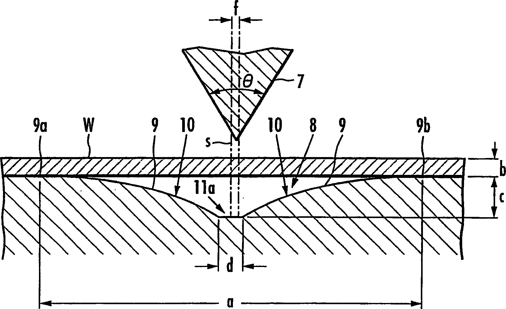
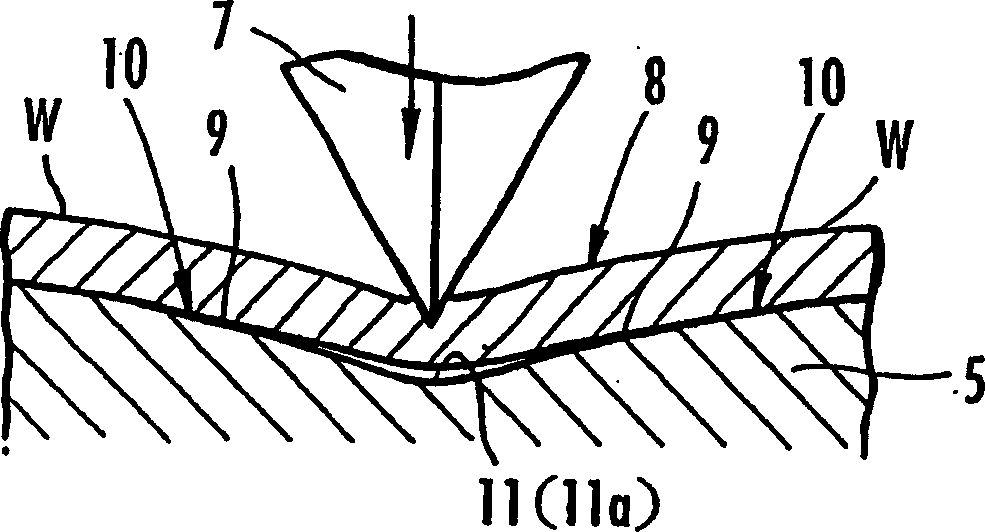
To provide a cutting device for a thin metal plate which can shorten the time for shaping the cut edge, improve manufacturing efficiency, and prolong the life of the cutter. The cutting device for cutting a metal thin plate (W) with a predetermined width is provided with a shear blade (7) made of a metal harder than the thin plate (W) and having a blade angle in the range of 50° to 90°. A contact tool (5) is provided with a groove (8) opposite to the shearing blade (7) and in contact with the inner side of the sheet (W). Set the spacing dimension (a) of the upper edge (9a, 9b) of the inner side wall (9) of the groove portion (8) as 15 to 30 times the plate thickness dimension (b) of the thin plate (W), and the groove portion (8) The depth dimension (c) of the deepest part (11) is set to 1 to 3 times the plate thickness dimension (b) of the thin plate (W). Curved surfaces (10) are provided on both inner side walls (9) of the groove portion (8), and the radius of curvature thereof is set to 15 to 50 times the thickness dimension (b) of the thin plate.

Description

technical field [0001] The present invention relates to a metal thin plate cutting device, and more particularly, to a metal thin plate cutting device suitable for cutting a cylindrical roll formed of a metal thin plate in a ring cut shape to form a plurality of metal rings. Background technique [0002] For example, in a power transmission belt employing a continuously variable transmission, a stacked ring formed by stacking a plurality of metal ring members is used in order to bind together a plurality of stacked ring-shaped elements. The metal ring constituting this kind of laminated ring is formed by cutting a cylindrical roller in a ring-cut shape to a predetermined width, and the cylindrical roller is formed by joining both end edges of a rectangular metal thin plate by welding. [0003] Conventionally, it is well known that when the above-mentioned metal ring is formed by cutting a cylindrical drum according to a predetermined width, one end portion of the support dru...

Claims


Application Information

Patent Timeline
Patent Type & Authority Applications(China)
IPC IPC(8): B23D21/00B23D19/00B23D33/08
Inventor 箕轮美幸芳贺文孝吉村刚长尾优一藤山武幸中村太郎
Owner HONDA MOTOR CO LTD
Learn More