Robot arm control method and control device

A manipulator and control mode technology, applied in the direction of manipulators, manufacturing tools, etc., can solve the problems of speed reduction, impossibility of ignoring interference force, etc., achieve the effects of reducing collision energy, improving target following characteristics, and solving deformation problems

Inactive Publication Date: 2006-05-10
PANASONIC CORP
View PDF13 Cites 40 Cited by
  • Summary
  • Abstract
  • Description
  • Claims
  • Application Information

AI Technical Summary

Problems solved by technology

[0106] Moreover, in the case of a vertical multi-joint robot, it is impossible to ignore the disturbing force between the axes
Then, it is possible to provide a speed-reducing force to one shaft whose speed should not be reduced by the disturbing force provided from the shaft to which the reverse torque is applied.

Method used


Image

  • Robot arm control method and control device
  • Robot arm control method and control device
  • Robot arm control method and control device

Examples


no. 1 example

[0144] FIG. 1 is a block diagram showing a control method of the present invention. In FIG. 1, reference numeral 26 is a velocity converting device, and reference numeral 27 is an angular velocity ω selected by the velocity converting device. The feedback current command I can be obtained in the following manner com (4): command θ from the rotation angle through the feedback controller (2) com (1) and the actual motor rotation angle θ fb A PID calculation is performed and a current limit (3) is performed. Regarding the current limit(3) Way , providing a system in which a limit is set and a system in which a feedback gain is reduced.

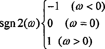
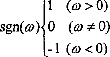
[0145] On the other hand, I can be calculated by expression (3) as follows ml (17). When turning the motor rotation command θ com (1) The angular acceleration α obtained when performing differential calculations (12) and (14) twice com (15) multiplied by the motor inertia J(16). Friction torque τμ(20) and dynamic torque τdyn(19) are adde...

no. 2 example

[0156] In the expression (12) showing the conversion of the speed in the first embodiment, at least one of the speed command value and the actual measurement value is multiplied by a weighting coefficient.

[0157] ω = ωfb ( | kcl * ωcom + kc 2 | ≤ | ωfb | ) ωcom ( | kcl * ωcom + kc ...

no. 3 example

[0162] Fig. 2 is a block diagram showing a control method of the third embodiment.

[0163] is input to the actual angular velocity ω of the velocity conversion device (26) fb (23) Multiplied by the friction compensation rate kμ.

[0164] It is expressed by Expression (15) as follows.

[0165] ω = k μ * ωfb ( | kcl * ωcom + kc 2 | ≤ | ωfb | ) ωcom ( | ...


PUM


Abstract

By appropriately selecting a command value or an actually measured value as the angular velocity used for friction torque calculation, friction compensation can be effective in both cases when actively operating according to the angular velocity command and passively operating, that is, when being pushed by an external force . Also, after a collision is detected, when the motor rotation direction is opposite to the collision direction, the position control is switched to current control so that the motor generates torque in the opposite direction to the motor rotation direction, thereby reducing the motor rotation speed and weakening the collision energy. Thereafter, when the motor rotation speed becomes the set value or lower, the mode is set to flexible control, thereby eliminating deformation of the speed reduction device or the like caused by the collision. On the other hand, when the motor rotation direction and the collision direction are the same, the position control is directly transferred to the flexibility control without going through the current control. By performing operations according to the collision force, it is possible to weaken the collision torque.

Description

technical field [0001] The invention relates to a method and a device for controlling a manipulator driven by a motor. More specifically, the present invention relates to a compliance servo control technique for controlling a manipulator, i.e. the invention relates to a method for controlling a manipulator stop after a collision with an object has been detected and equipment. Background technique [0002] Recently, robots have been used not only in industrial fields but also in public consumer fields. Therefore, ensuring security has become important. However, according to the stopper that stops the robot by detecting an external force applied to the robot at the time of collision using a force sensor, manufacturing cost and weight undesirably increase. Thus, it is desirable to enhance the performance of compliant servo control, including collision detection, and to enhance the performance of stop-motion control without the use of sensors. [0003] As for the method for ...

Claims


Application Information

Patent Timeline
Patent Type & Authority Applications(China)
IPC IPC(8): B25J13/00
Inventor 中田广之增永直人桥本敦实向井康士
Owner PANASONIC CORP
Why Eureka
Try Eureka