
Push-pull ortho-exciting three-level DC inverter

A push-pull forward, three-level technology, applied in the direction of converting DC power input to DC power output, adjusting electrical variables, instruments, etc., can solve the problems of large output filter and large change in duty cycle, and achieve reduction Effects of small voltage rating, reduced conduction loss, and improved conversion efficiency

Inactive Publication Date: 2006-05-17
NANJING UNIV OF AERONAUTICS & ASTRONAUTICS
View PDF0 Cites 4 Cited by
  • Summary
  • Abstract
  • Description
  • Claims
  • Application Information

AI Technical Summary

Problems solved by technology

The push-pull forward DC converter has also received extensive attention because it can reduce the input filter, but in the case of wide-range low-voltage input and high-voltage output, the duty cycle changes greatly, and the output filter is large.

Method used

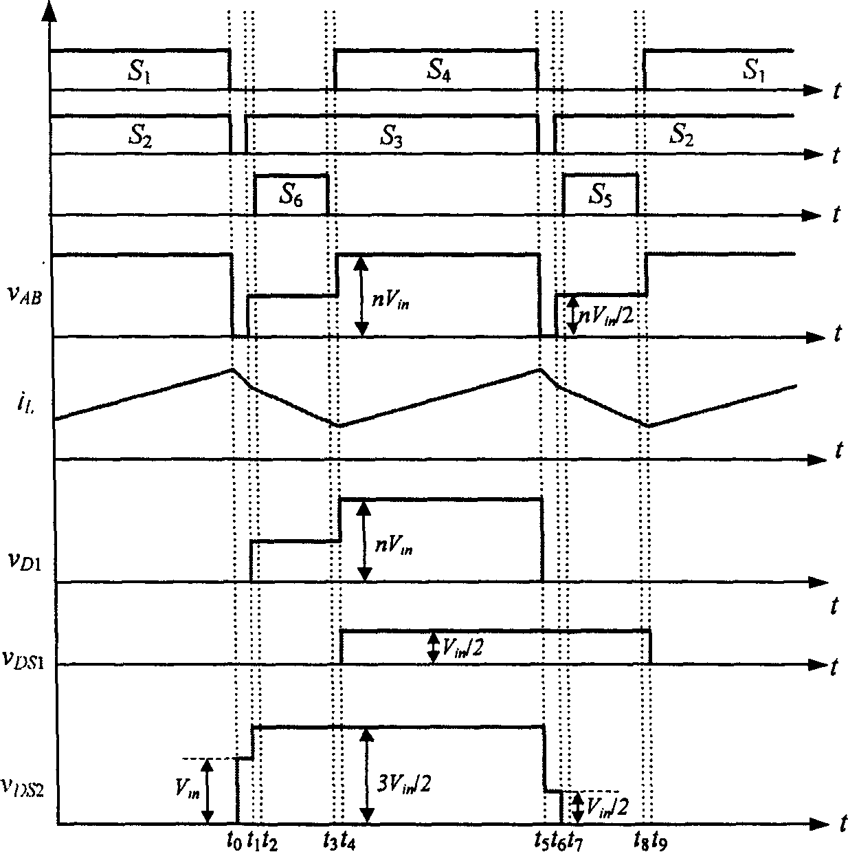
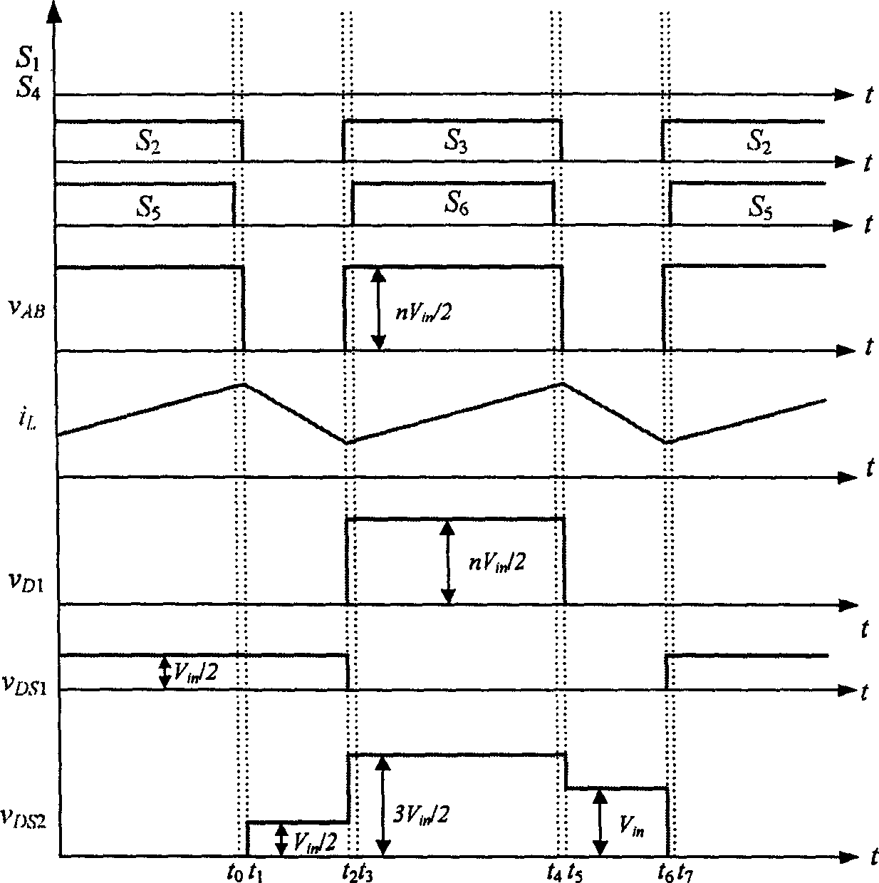

Image

  • Push-pull ortho-exciting three-level DC inverter
  • Push-pull ortho-exciting three-level DC inverter
  • Push-pull ortho-exciting three-level DC inverter

Examples


Embodiment Construction

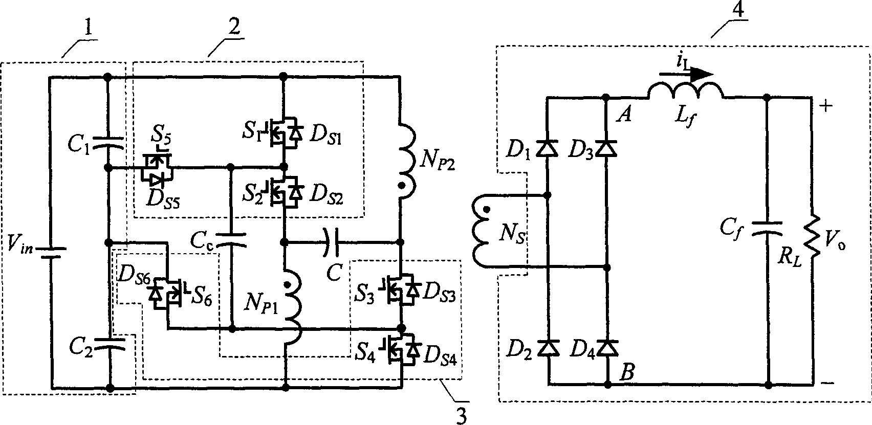
[0011] The specific embodiment of the present invention will be described according to the accompanying drawings. Depend on figure 1 It can be seen that the main circuit of the push-pull forward three-level DC converter of the present invention consists of an input voltage dividing capacitor circuit 1, two three-level branches 2, 3, and a flying capacitor C c , Clamp capacitor C, isolation transformer, rectifier bridge and filter circuit 4 components. where the voltage divider capacitor C 1 and C 2 The capacity is large and equal, and its voltage is the input voltage V in half of the V c1 =V c2 =V in / 2, which can be regarded as a voltage of V in / 2 voltage source. Three power switch tubes S 1 , S 2 , S 5 and its antiparallel diode D S1 、D S2 、D S5 Form a three-level branch 2; three power switch tubes S 3 , S 4 , S 6 and its antiparallel diode D S3 、D S4 、D S6 Another three-level branch 3 is formed. N P1 , N P2 , N S They are the two primary and seconda...


PUM


Abstract

A inverter of push ¿C pull normal shock three ¿C level DC is prepared as connecting two ends of clamping capacity separately to crossover point of isolation transformer primary winding and three ¿C level branch ad well as crossover point of isolation transformer primary winding b and three ¿C level branch b, connecting the crossing capacity to connection point of power switching tubes on two three ¿C level branches, connecting isolation transformer secondary winding to rectifying and filtering circuit.

Description

1. Technical field [0001] The push-pull forward three-level DC converter of the invention belongs to the DC converter of an electric energy conversion device. 2. Background technology [0002] In recent years, the application of three-level DC converters in high-voltage applications has received widespread attention, because its power switch tube voltage stress is only half of the input voltage; some three-level converters can also reduce the output filter, Because the high-frequency AC components at both ends of the output filter are small. However, there are few studies on three-level converters in low-voltage input and high-voltage output situations, and the control adopted is to make the output rectified three-level waveform first appear at a high level, and then appear at a half-voltage level. In this way, in the case of low-voltage input and high-voltage output, the voltage peak of the output rectifier diode caused by the leakage inductance of the transformer and the ...

Claims


Application Information

Patent Timeline
IPC IPC(8): H02M3/337
Inventor 姚志垒肖岚严仰光
Owner NANJING UNIV OF AERONAUTICS & ASTRONAUTICS
Learn More