Expansion device

A technology of expansion device and differential pressure valve, which is applied in fluid circulation arrangement, refrigeration components, refrigerators, etc., can solve the problems of increasing the cost of expansion device and rupture of closed space, etc.

Inactive Publication Date: 2006-05-24
TGK
View PDF1 Cites 16 Cited by
  • Summary
  • Abstract
  • Description
  • Claims
  • Application Information

AI Technical Summary

Problems solved by technology

[0007] However, conventional expansion devices are constructed so that they include a closed space sealed by a displacement member to sense the pressure and temperature of the introduced refrigerant to vary the valve lift, and the closed space is charged with the refriger

Method used


Image

  • Expansion device
  • Expansion device
  • Expansion device

Examples


Embodiment Construction

[0029] Hereinafter, an embodiment of the present invention will be described in detail based on an example applied to using CO 2 in the refrigeration cycle.

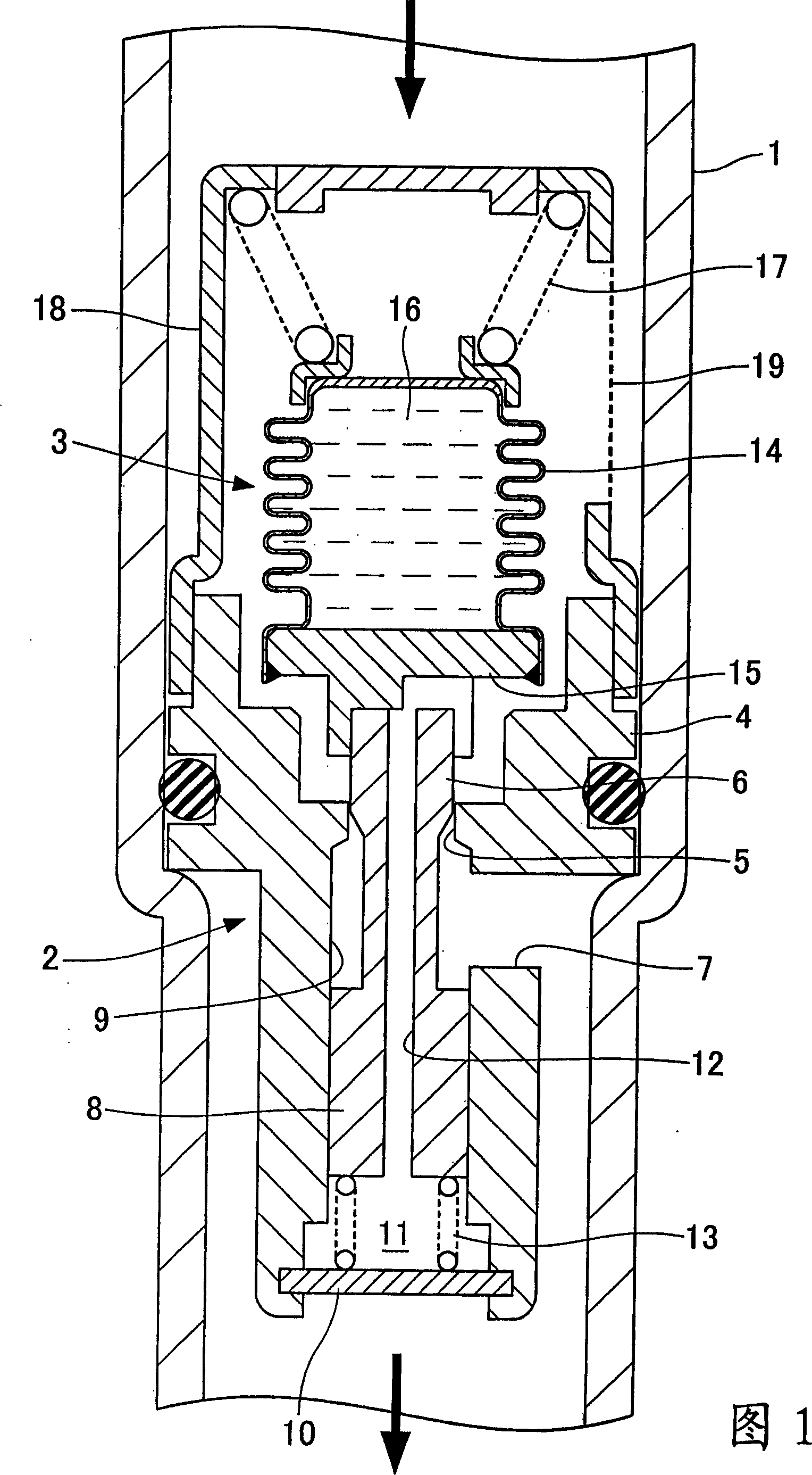
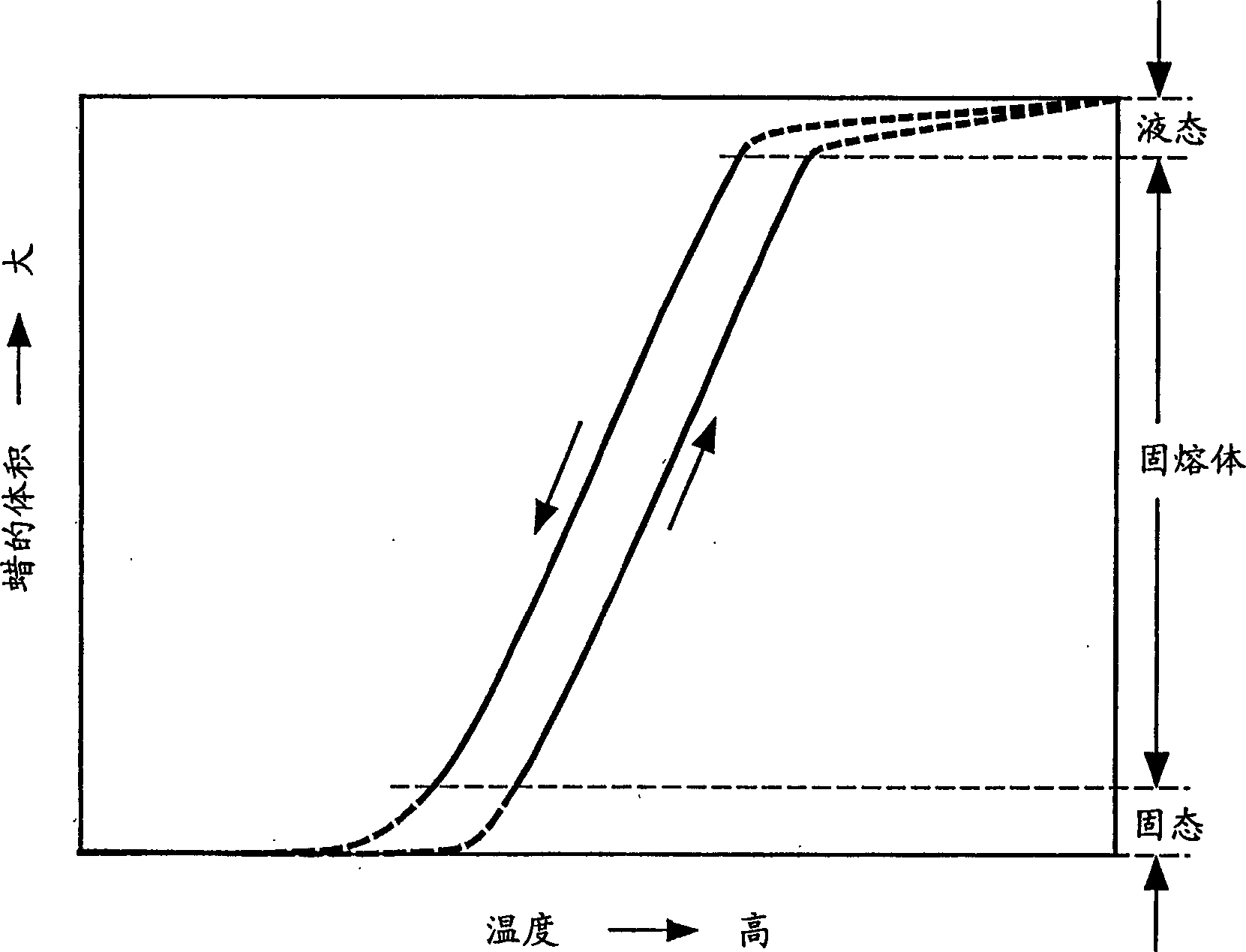
[0030] 1 is a central longitudinal sectional view of an expansion device structure according to a first embodiment of the present invention, and figure 2 is a graph showing the temperature characteristics of the temperature sensing section.

[0031] The expansion device according to the first embodiment is arranged in a pipe 1 between the gas cooler and the evaporator of the refrigeration cycle for circulating the refrigerant. The expansion device includes: a differential pressure valve 2 whose valve lift is controlled according to the pressure difference across the expansion device; a temperature sensing part 3 which further controls the valve lift of the differential pressure valve 2 according to the inlet temperature of the refrigerant. It should be noted that, as shown in Figure 1, the upper part of the pipe 1 corr...


PUM


Abstract

Provided is a low-cost expansion device capable of changing the passage cross-sectional area of ​​the throttling passage according to the pressure and temperature of the introduced refrigerant without providing a high-pressure closed space. The expansion device includes: a differential pressure valve for having its valve lift controlled according to a pressure difference across the expansion device; and a temperature sensing portion for further controlling the pressure difference according to refrigerant temperature The valve lift of the valve. The differential pressure valve includes a piston having a larger outer diameter than the valve element and integrally formed with the valve element. The piston forms a pressure regulating chamber into which the inlet pressure of the refrigerant is introduced through the pressure channel, so that when the inlet pressure of the refrigerant becomes higher, the differential pressure valve is operated in the valve opening direction. The temperature sensing part is formed by filling wax having a large bulk expansion coefficient into a bellows that can expand and contract axially, thereby operating the differential pressure valve in a valve-closing direction when the refrigerant inlet temperature becomes high.

Description

technical field [0001] The present invention relates to an expansion device used in a refrigerating cycle for an automobile air conditioner, and more particularly to such an expansion device applicable to the use of carbon dioxide (CO 2 ) of the refrigeration cycle and be able to operate the refrigeration cycle efficiently. Background technique [0002] As a refrigeration cycle for automobile air conditioners, not only is known a refrigeration cycle in which a receiver is used to separate refrigerant condensed by a condenser into gas and liquid, and a thermostatic expansion valve is used to separate the refrigerant obtained from gas / liquid separation The liquid refrigerant expands, and a refrigeration cycle is known in which the refrigerant condensed by the condenser is throttled and expanded using a restrictor tube, and the refrigerant evaporated by the evaporator is separated into gas and liquid. The restrictor tube is formed of a small-diameter tube, so that its structu...

Claims


Application Information

Patent Timeline
IPC IPC(8): F25B41/06
Inventor 广田久寿
Owner TGK
Why Eureka
Try Eureka