Six-dimensional force sensor integrated strain gauge

A six-dimensional force sensor and strain gauge technology, which is applied in the direction of instruments, measuring force, and measuring devices, can solve the problems of large number of wires, cumbersome pasting, difficulty in guaranteeing strain consistency and pasting accuracy, and achieve high measurement accuracy and reduce Pasting workload, effect of ensuring pasting position accuracy and strain consistency

Inactive Publication Date: 2006-05-24
HARBIN INST OF TECH
View PDF1 Cites 26 Cited by
  • Summary
  • Abstract
  • Description
  • Claims
  • Application Information

AI Technical Summary

Problems solved by technology

[0003] The purpose of the present invention is to solve the existing multi-dimensional force sensor, each piece of strain gauge needs to be pasted on the cylindrical elastic body one by one during use, so there

Method used


Image

  • Six-dimensional force sensor integrated strain gauge
  • Six-dimensional force sensor integrated strain gauge
  • Six-dimensional force sensor integrated strain gauge

Examples


specific Embodiment approach 1

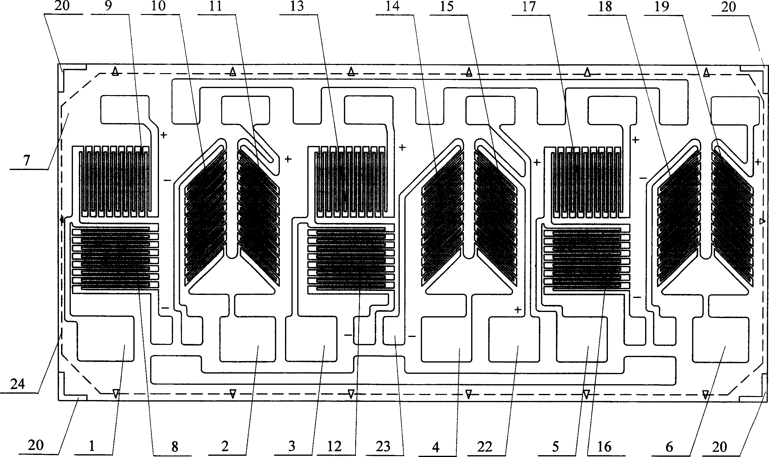
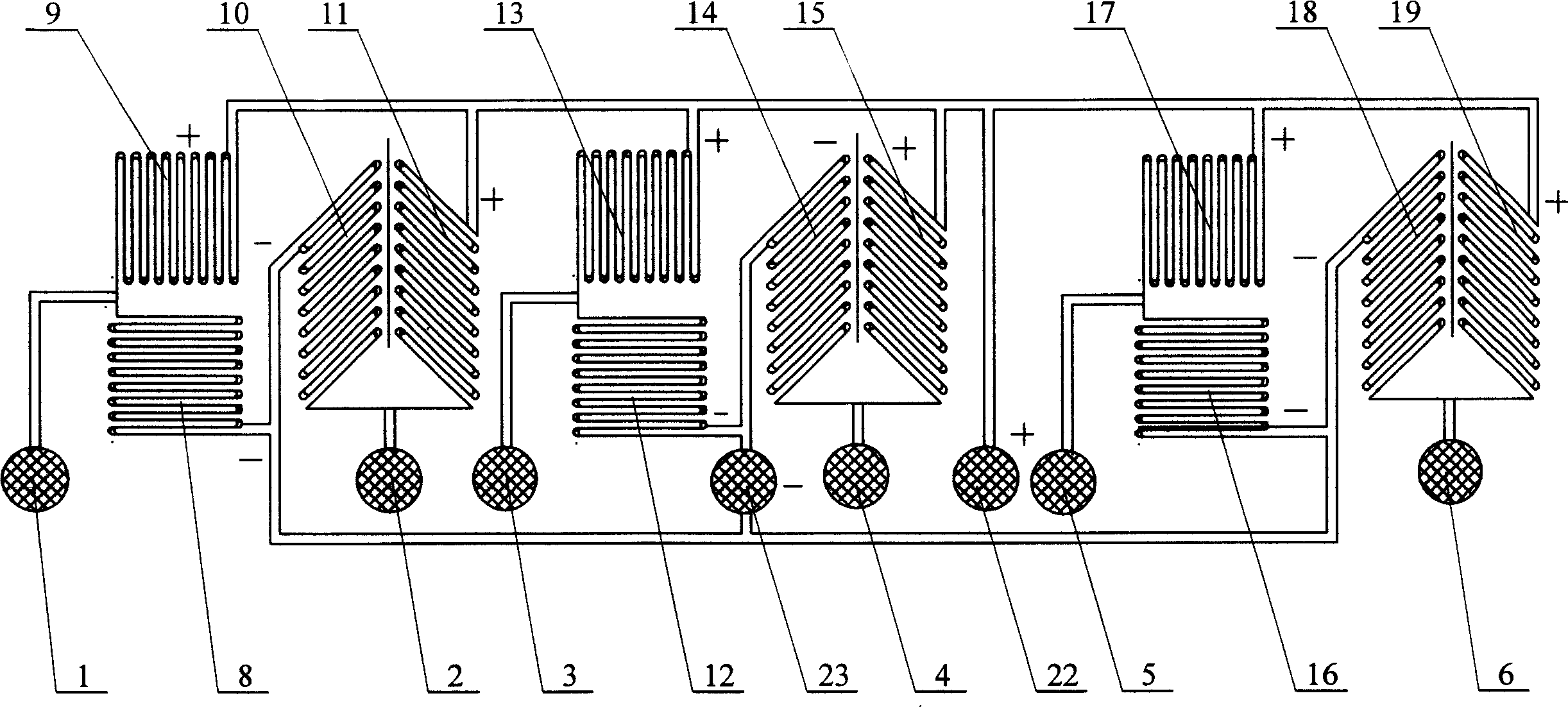
[0006] Specific implementation mode one: combine figure 1 , figure 2 Describe this embodiment, this embodiment is made up of sheet base 7 and the strain gage 24 that is fixed on the upper surface of sheet base 7; Described strain gage 24 is made up of three groups of 90 ° mode double gate and three groups of shear mode Double gates are placed side by side and arranged alternately. Each set of 90° mode double gates and each set of shear mode double gates constitute a half-bridge measurement circuit respectively. Three sets of 90° mode double gates constitute the first half bridge measurement circuit and the third half bridge respectively. The bridge measurement circuit and the fifth half-bridge measurement circuit, three sets of shear mode double gates respectively constitute the second half-bridge measurement circuit, the fourth half-bridge measurement circuit and the sixth half-bridge measurement circuit, and the first half-bridge measurement circuit in the first half-bridge...

specific Embodiment approach 2

[0007] Specific implementation mode two: combination figure 1 Describe this embodiment, the difference between this embodiment and specific embodiment 1 is: this embodiment also adds a marking component 20; said marking component 20 is respectively fixed on the four vertices of the upper surface of the sheet-shaped base 7 Above; the marking component 20 is in the shape of a right angle. Using the marking component 20 as a reference for pasting the strain gauges 24 can ensure that the pasting positions of the strain gauges 24 are consistent when pasting the strain gauges 24 . Other components and connections are the same as those in the first embodiment.

specific Embodiment approach 3

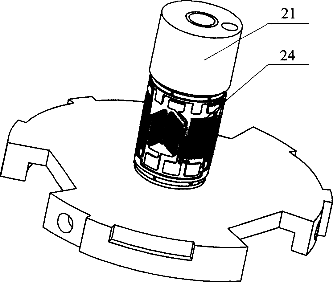
[0008] Specific implementation mode three: combination image 3 , Figure 4 , Figure 5 Describe this embodiment, the overall size (length×width) of the strain gauge of this embodiment is 12.57×6mm, stick on the sensitive area of ​​the cylindrical elastic body 21 that diameter Φ is 4mm, height H is 6mm, exactly one circle, each The resistance value of the sensitive grid is 375Ω.


PUM

PropertyMeasurementUnit
Resistanceaaaaaaaaaa

Abstract

The disclosed integrated strainmeter includes substrate and strain gauges fixed on the substrate. Strain gauges are composed of three sets of dual-gate in 90 degree mode and three sets of dual-gate in shear mode alternant arranged in parallel. Each set of dual-gate in 90 degree mode and each set of dual-gate in shear mode constitute a half bridge measuring circuit. Each half bridge measuring circuit possesses a signal output end. Being connected to each other, positive pole end of each half bridge measuring circuit is connected to power source. Being connected to each other, negative pole end of each half bridge measuring circuit is connected to ground. Comparing with prior art, the invention solves issues of fussy sticking procedure, difficult to guarantee consistency of strain and too many leads, and possessing advantages of high precision, less number of leads and one time of procedure for sticking strain gauges on columniform elastic body.

Description

technical field [0001] The invention relates to a multi-dimensional force sensor strain gauge, in particular to a six-dimensional force sensor integrated strain gauge. Background technique [0002] Multi-dimensional force sensors generally adopt a compound structure with complex structure and difficult processing. Usually the elastic strain area is distributed in different planes and different regions of the elastic body, so it is necessary to paste multiple strain gauges with different numbers, and each strain gauge needs to lead out several wires, so there are the following problems: 1. Multi-dimensional The elastic body of the force sensor is complex in structure, difficult to process, and difficult to guarantee the consistency of strain; 2. The number of strain gauges pasted is large, the pasting work is heavy, and the pasting quality and pasting position accuracy are difficult to guarantee; 3. The number of strain gauge leads is large, and its connection quality and Re...

Claims


Application Information

Patent Timeline
IPC IPC(8): G01L1/22
Inventor 王嘉力刘宏高晓辉姜力
Owner HARBIN INST OF TECH
Why Eureka
Try Eureka