
Top hood assembly of closed compressor

A compressor, a closed technology, applied in the field of compressors, can solve the problems of large vibration and noise, vibration of the discharge pipe 12, short passage, etc., achieve good pulsation and noise, and reduce noise and pulsation

Inactive Publication Date: 2006-05-31
LG ELECTRONICS (TIANJIN) APPLIANCES CO LTD
View PDF0 Cites 2 Cited by
  • Summary
  • Abstract
  • Description
  • Claims
  • Application Information

AI Technical Summary

Problems solved by technology

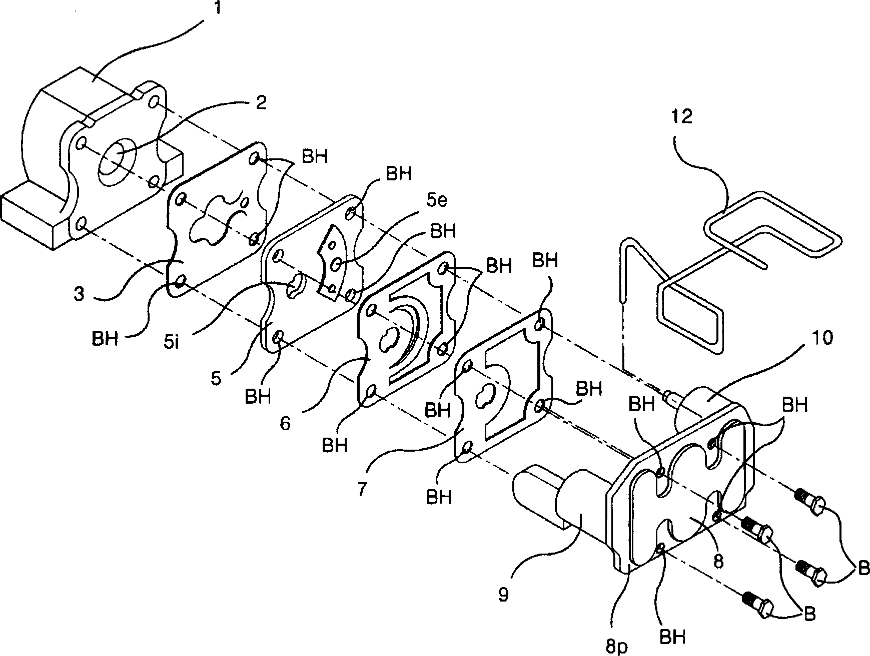
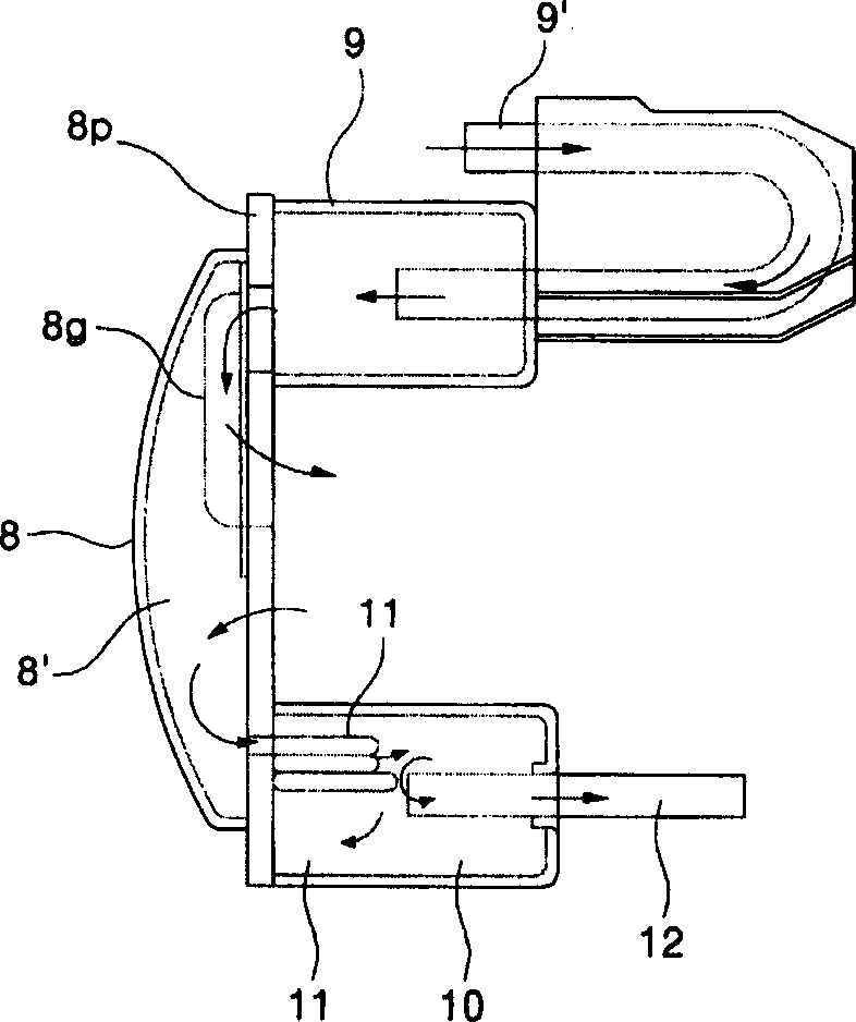
[0011] However, under the conventional technology, the path from the compression chamber 2 to the discharge pipe 12 is relatively short, and the pulsation of the working fluid flowing inside cannot be completely eliminated.
As a result, the fluttering phenomenon of the discharge pipe 12 is caused, and large vibration and noise are generated.

Method used


Image

  • Top hood assembly of closed compressor
  • Top hood assembly of closed compressor
  • Top hood assembly of closed compressor

Examples


Embodiment Construction

[0036] Below in conjunction with accompanying drawing and specific embodiment the present invention is described in further detail:

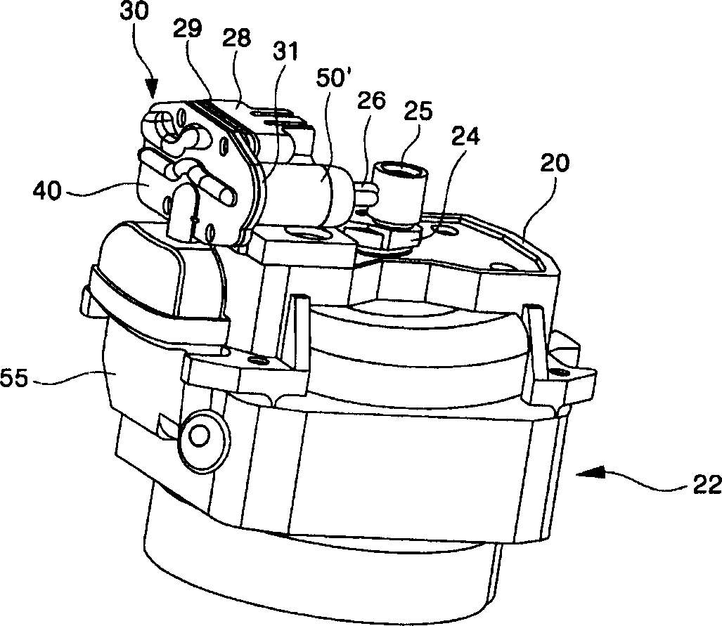
[0037] First, the process of compressing the working fluid by the compressor of the present invention will be described. When the motor unit 22 operates, the crankshaft 24 rotates. Under the action of the rotation of the crankshaft 24 , the eccentric member 25 performs a circular motion, and one end of the connecting rod 26 connected thereto moves together with the eccentric member 25 . The piston connected to the other end of the connecting rod 26 performs linear reciprocating motion inside the compression chamber of the cylinder 28 to compress the refrigerant.

[0038] The working fluid flows through the suction muffler 55 and is directed to the compression chamber. That is, the working fluid whose noise has been eliminated in the suction muffler 55 flows into the compression chamber under the control of the valve assembly 29 .

[0039] As ...


PUM


Abstract

A top cover for a closed compressor comprises a top board and a cover board. A hole on the top board is linked to the outlet of the compress chamber; the two ends of the hole are jointed with the first and the second mufflers. A concave convex joint part is fixed on the cover board to form a channel for liquid flowing from the outlet hole and the mufflers. The two mufflers are posited to the two ends of the top cover and form the channel with the concave convex joint part. The design prolongs outlet way of liquid so to minimize noise and pulsation.

Description

technical field [0001] The invention relates to compressors, in particular to a hermetic compressor top cover assembly. In more detail, the top shroud assembly forms passages through which the working fluid flows into and out of the compression chamber. Background technique [0002] A compressor is a device that compresses the working fluid of a heat exchange system. figure 1 It is an exploded schematic diagram of the structure of the main parts of the traditional hermetic compressor. This figure shows the structure of compressor suction and discharge working fluid. As shown in the figure, a compression chamber 2 is formed inside the cylinder 1 . In addition, a valve assembly is formed on the cylinder 1 . The valve assembly is used to suck working fluid into the compression chamber 2 or discharge the sucked working fluid to the outside of the compression chamber 2 . [0003] The valve assembly described above includes a suction valve 3 , a valve plate 5 , a discharge va...

Claims


Application Information

Patent Timeline
Patent Type & Authority Applications(China)
IPC IPC(8): F04B39/00F04B27/10
Inventor 金泰民
Owner LG ELECTRONICS (TIANJIN) APPLIANCES CO LTD
Learn More