
Evaporator and its manufacturing method

A technology for evaporator and refrigerant circulation, which is applied in the field of evaporator and its manufacturing, can solve the problems that need to be improved, and achieve the effect of suppressing odor emission

Inactive Publication Date: 2006-05-31
SHOWA DENKO KK
View PDF1 Cites 9 Cited by
  • Summary
  • Abstract
  • Description
  • Claims
  • Application Information

AI Technical Summary

Problems solved by technology

[0009] However, the evaporators manufactured by the methods disclosed in the above publications still need to be improved in terms of completely reducing the odor emission caused by flux residues

Method used


Image

  • Evaporator and its manufacturing method
  • Evaporator and its manufacturing method
  • Evaporator and its manufacturing method

Examples


example 1-4

[0077] A flux suspension comprising flux (FL-7, product of Morita Kagaku Co., Ltd.) suspended in water containing a binder (SURFBEST 1100, product of NIPPON PAINT Co., Ltd.) was prepared. A Z-shaped flat tube made of aluminum extruded profile, a corrugated fin made of aluminum brazing sheet with layers of brazing material on both sides, aluminum side plates and two kinds of aluminum headers were prepared.

[0078] Various amounts (calculated from the flux itself) of the flux suspension were applied by brushing to the entire outer surface of the zigzag flat tube. Then, corrugated fins are arranged between each pair of adjacent straight pipe parts of each zigzag pipe, two corrugated fins are arranged outside each straight pipe part at both ends of the pipe, and two side plates are arranged on the The exterior of the corrugated fins at each end, the two headers are connected to the ends of the zigzag tube and the resulting assembly is secured with suitable clamps.

[0079] Subse...


PUM


Abstract

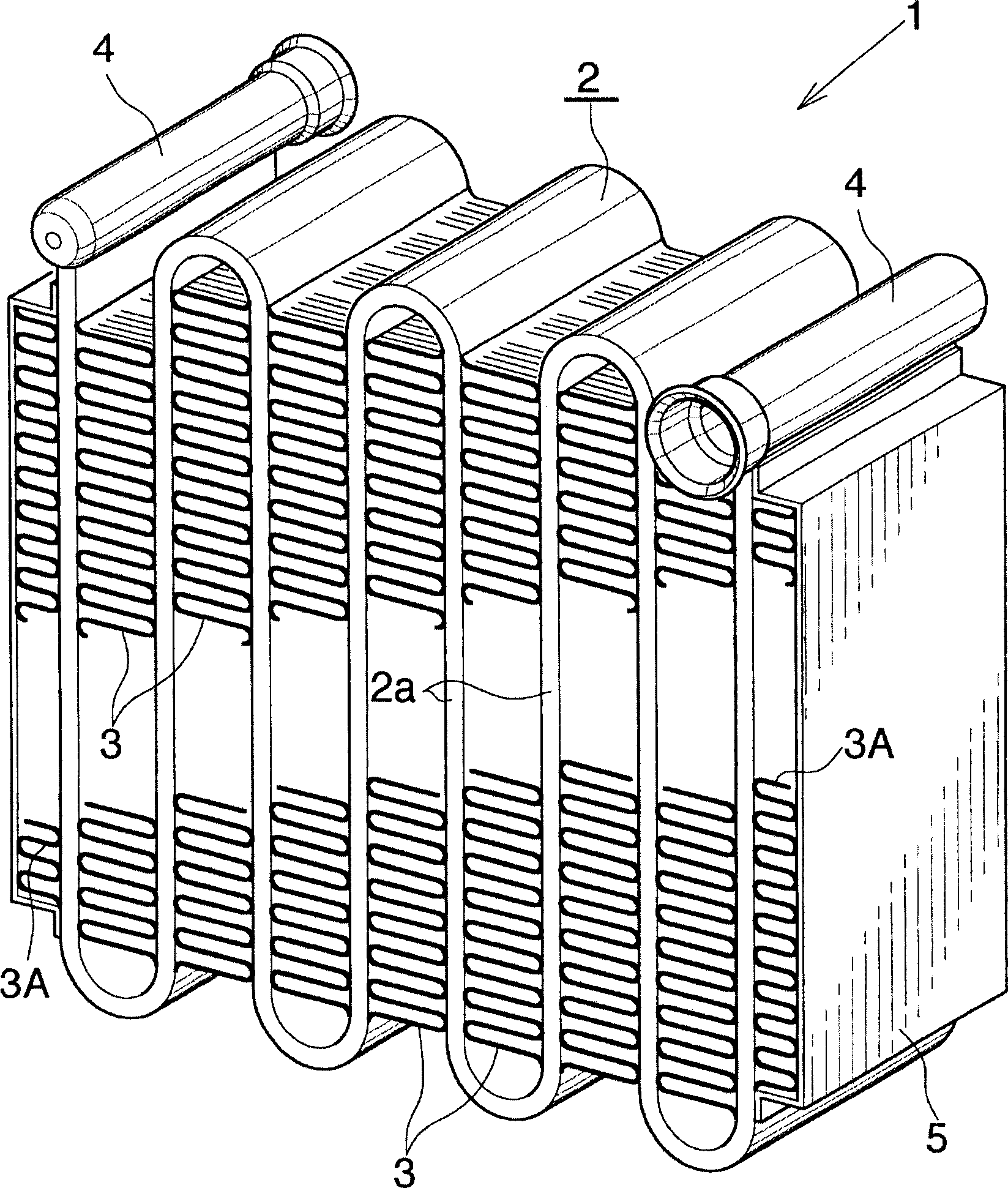
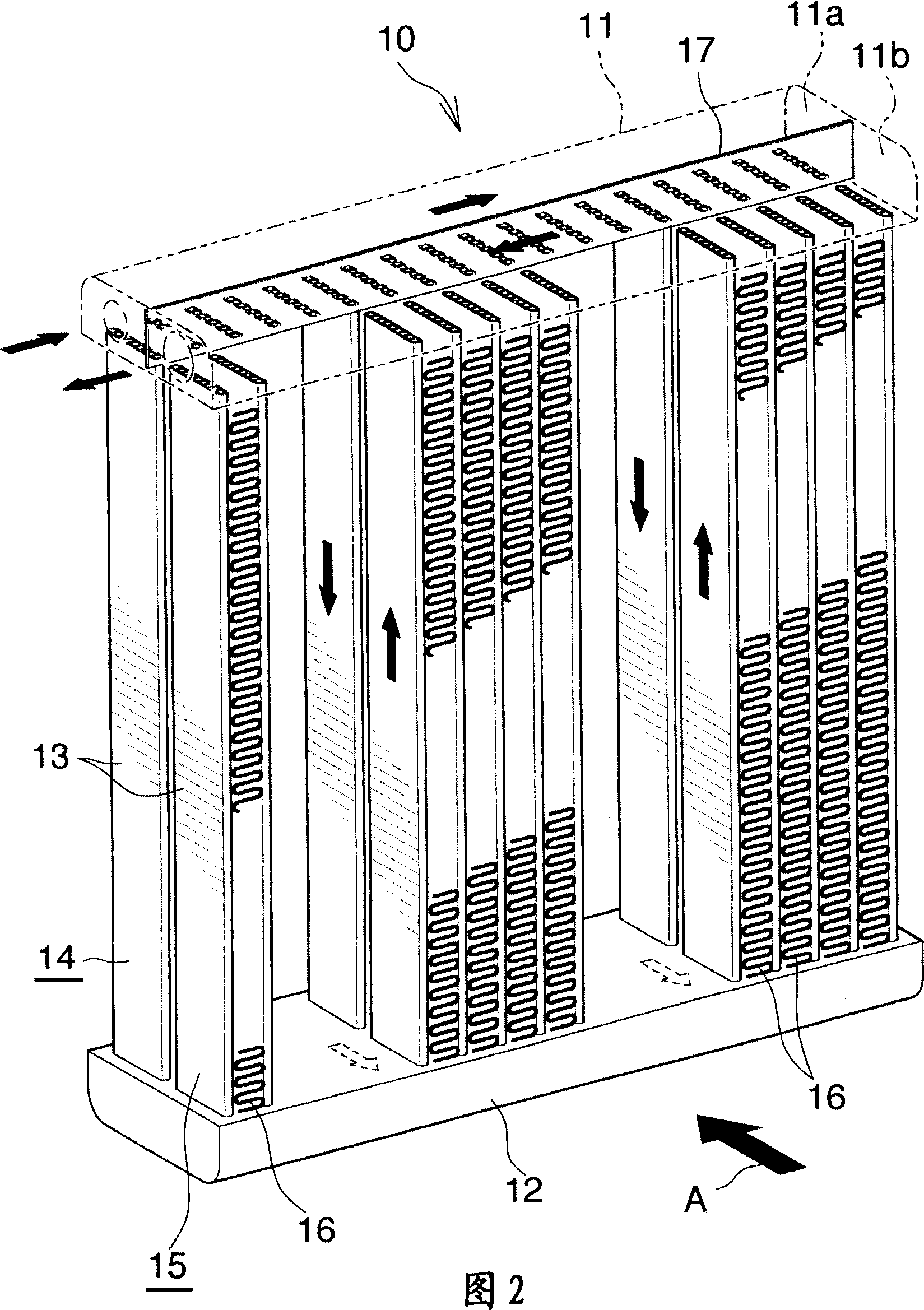
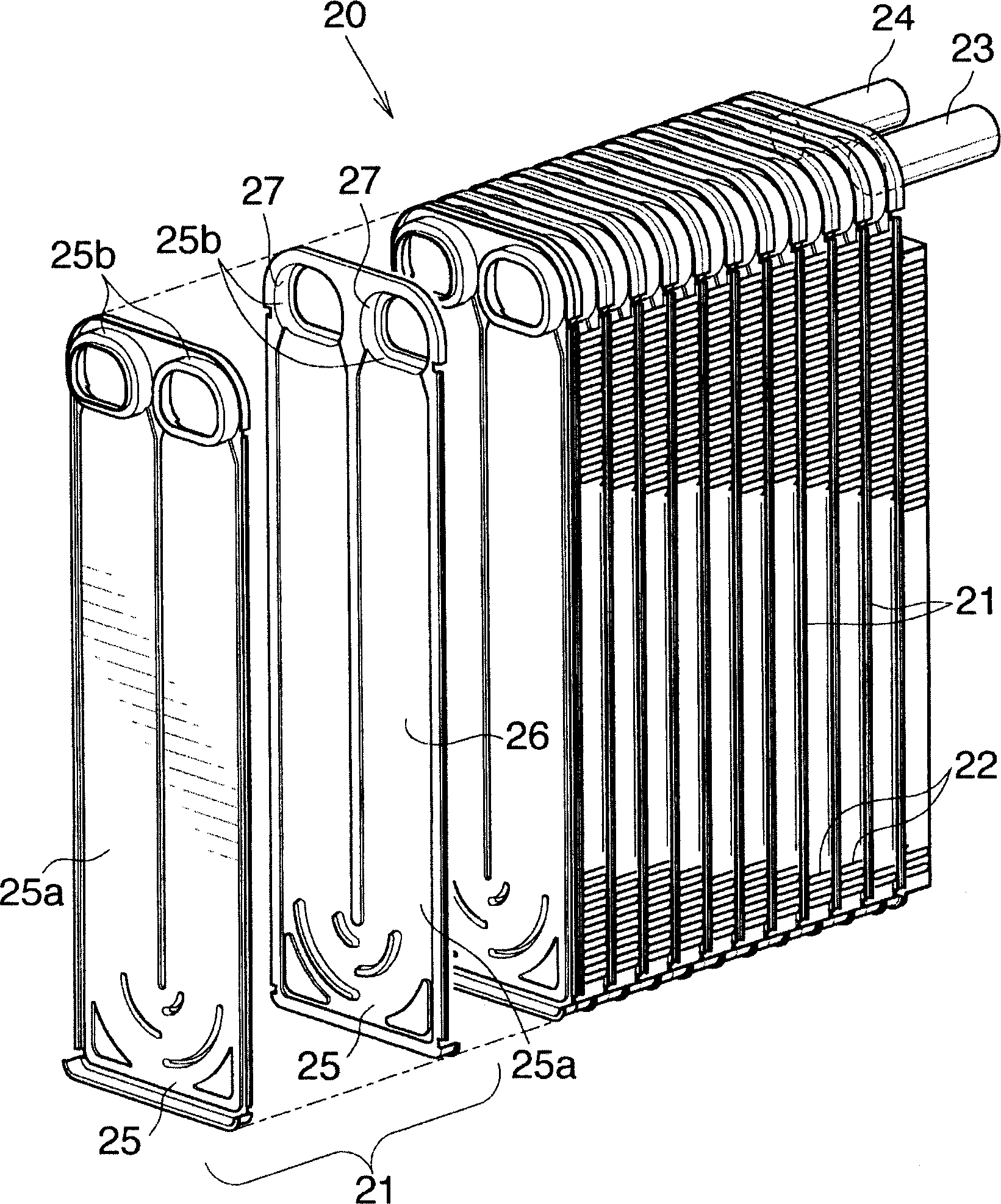
The invention discloses an evaporator (1), which comprises a zigzag flat tube (2) arranged between each pair of adjacent straight tube parts (2a) of the flat tube (2) and brazed by flux corrugated fins (3) brazed thereon. The amount of flux remaining on the surface of the portion of the corrugated fin (3) that is not brazed to the straight pipe portion (2a) is 0.03-1 g / m2. The evaporator (1) is manufactured by applying 0.05-2.8g / m2 flux on the outer surface of the Z-shaped flat tube (2), and setting the corrugated fins (3) on the flat tube (2) ) between each pair of adjacent straight tube parts (2a), and the fins (3) are brazed on the flat tubes (2). The evaporator (1) can effectively suppress the emission of odor.

Description

[0001] Cross References to Related Applications [0002] This application is an application filed under 35 U.S.C. § 111(a) and a provisional application filed under 35 U.S.C. § 111(b) under 35 U.S.C. § 111(b) under 35 U.S.C. § 119(e)(1) Priority filing date for No. 60 / 477,746. technical field [0003] The present invention relates to evaporators and methods for their manufacture, in particular for example for use in which chlorofluorocarbon refrigerants or CO 2 An evaporator for a motor vehicle air-conditioning system for a refrigerant, and a method for manufacturing the evaporator. Background technique [0004] Evaporators of the type comprising hollow bodies through which the refrigerant flows and corrugated fins (brazed) brazed on the outer surface of the adjacent hollow bodies are widely used. [0005] This evaporator is manufactured by combining a hollow body through which the refrigerant circulates and corrugated fins, spraying a flux suspension prepared by suspendin...

Claims


Application Information

Patent Timeline
IPC IPC(8): F28F1/30
Inventor 中川信太郎
Owner SHOWA DENKO KK
Learn More