

Belt speed reducer for electric power steering device and electric power steering device
A technology of electric power steering and deceleration device, applied in the direction of electric steering mechanism, etc., can solve the problems of belt tension fluctuation and adverse effect on the performance of electric power steering device, and achieve the effect of improving durability, reducing friction noise and loss, and reducing friction noise.
- Summary
- Abstract
- Description
- Claims
- Application Information
AI Technical Summary
Problems solved by technology
Method used
Image

Examples
no. 1 example
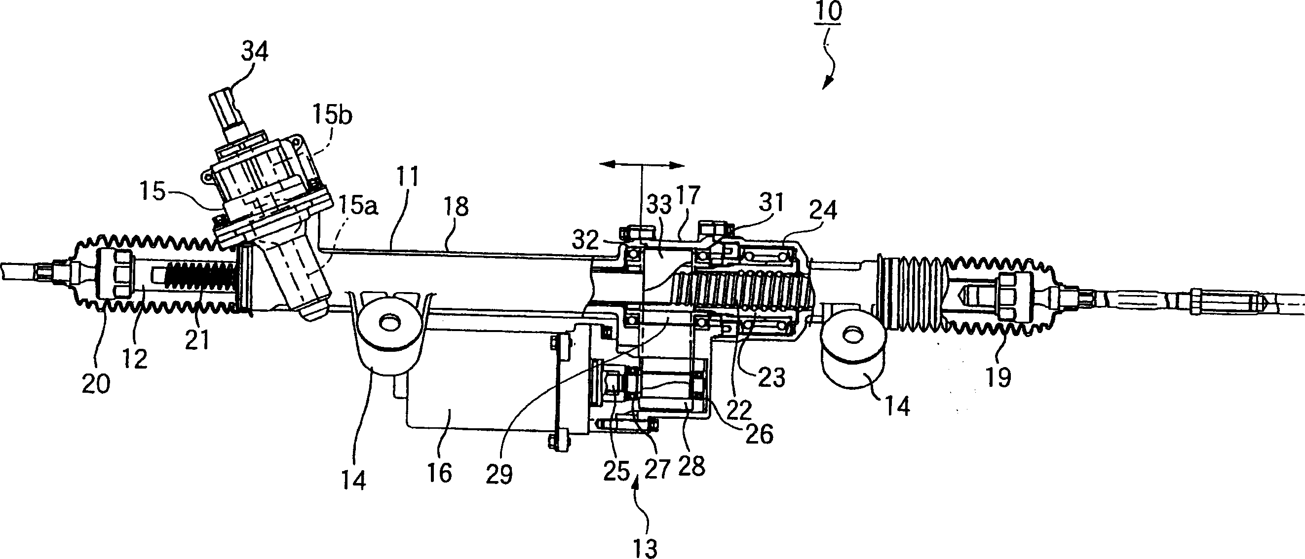
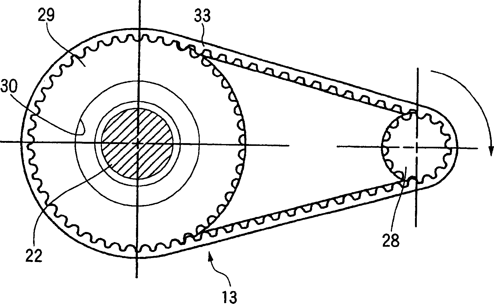
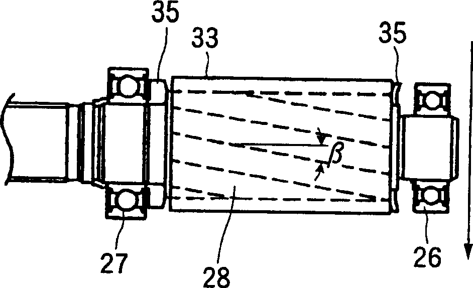
[0165] First, refer to Figure 1 to Figure 4 A belt speed reduction device for an electric power steering device and an electric power steering device according to a first embodiment of the present invention will be described in detail.
[0166] The electric power steering device 10 of the first embodiment includes a cover 11 , a rack shaft 12 , a belt reduction gear 13 , a vehicle body mounting portion 14 , a pinion portion 15 , and an auxiliary motor 16 .
[0167] The cover 11 is divided into two substantially at the center, and has a bisected structure composed of a right cover 17 and a left cover 18 . The rack shaft 12 is supported by the cover 11, and is movable in the axial direction within the cover 11, but is prevented from rotating. Both ends of the rack shaft 12 protrude from both ends of the cover 11 . A body-side steering mechanism for changing the direction of the wheels, such as a tie rod, is connected to both ends. The protruding parts are respectively covere...
no. 2 example
[0178] Second, refer to Figure 5 and Figure 6 An electric power steering apparatus according to a second embodiment of the present invention will be described. In addition, in this embodiment, a gear reduction mechanism using helical gears is employed.
[0179] In the electric power steering device 40 of the second embodiment, an assist motor 41 has a stator 42 and a rotor 43 , and an extension 45 is fixed to one end of a motor shaft 44 fixed to the rotor 43 . The extension 45 of the motor shaft 44 is supported by a bearing 47 held by a motor flange 46 , and the other end of the motor shaft 44 is supported by a bearing 49 held by a motor cover 48 , so that the motor shaft 44 is rotatably supported.
[0180] In order to avoid interference between the motor cover 48 and the rack shaft cover 50 , the distance between the shaft centers of the input gear 51 and the output gear 52 is increased, and the input gear 51 and the output gear 52 are meshed through the intermediate gear...
no. 3 example
[0193] Second, refer to Figure 7 An electric power steering apparatus according to a third embodiment of the present invention will be described. Also, in this embodiment, a gear reduction mechanism using helical gears is employed. Additionally, along the Figure 7 Sectional view of line VI-VI with Figure 6 The shown figures are the same, so illustration is omitted.
[0194] The difference between the third embodiment and the second embodiment is: the motor shaft 44 and the input gear 51 are integrated, and are held by three bearings 49, 47 and 59; The inner ring of the bearing 59 is pressed to apply preload to the bearing 47 and the bearing 59 to prevent vibration in the axial direction. Since other structures are the same as those of the second embodiment, the same symbols are used for the same components, and detailed descriptions are omitted.
[0195] In the electric power steering device 90 of the third embodiment, the adjustment of the backlash is also the same as...
PUM
 Abstract
Description
Claims
Application Information