Retainer for roller bearing

A roller bearing and cage technology, applied in the field of cages, can solve the problems of low wear resistance, low bending stress and mechanical strength, and achieve the effects of preventing abnormal wear, improving mechanical strength, and inhibiting wear.

Inactive Publication Date: 2006-06-07
NSK LTD
View PDF2 Cites 8 Cited by
  • Summary
  • Abstract
  • Description
  • Claims
  • Application Information

AI Technical Summary

Problems solved by technology

In addition, on the surface of the pin where the surface hardening layer is not formed, in addition to the lower wear resistanc

Method used


Image

  • Retainer for roller bearing
  • Retainer for roller bearing
  • Retainer for roller bearing

Examples


Embodiment Construction

[0074] Embodiments of the present invention will now be described with reference to the drawings.

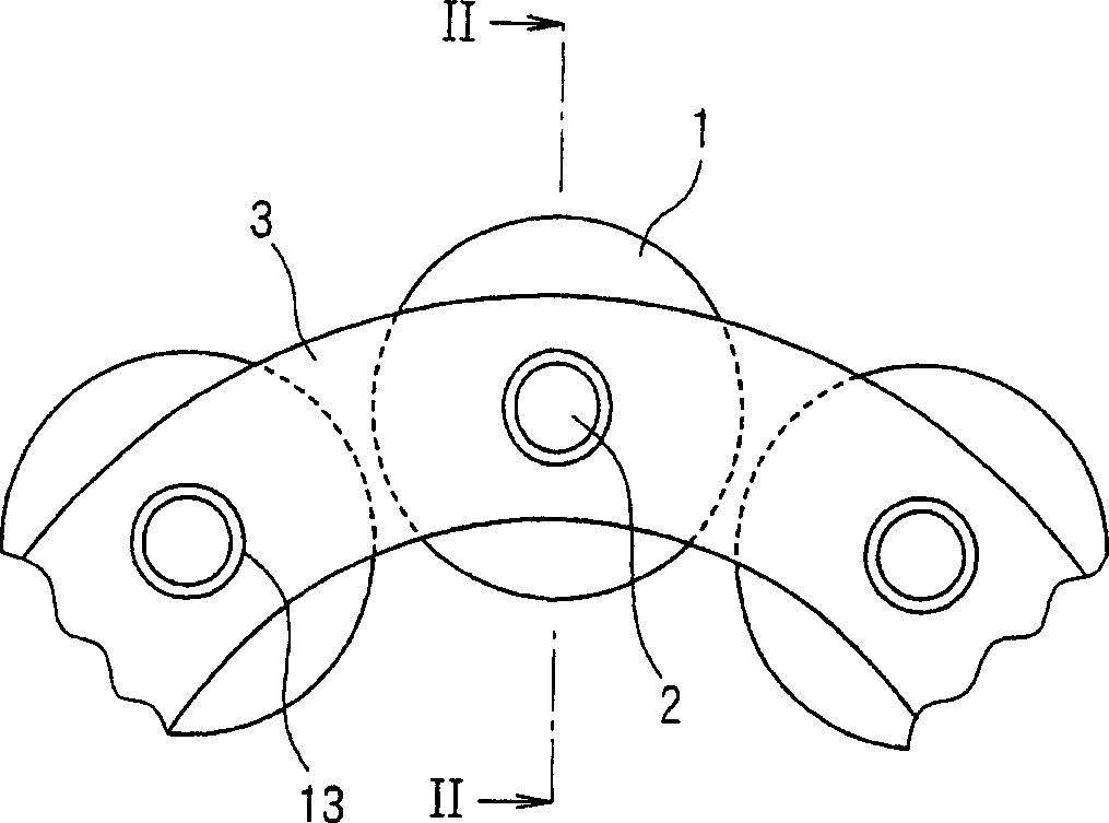
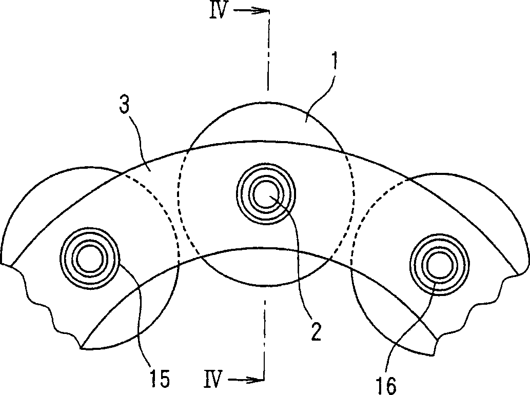
[0075] According to a first embodiment of the invention, a cage for a roller bearing comprises a plurality of pins 2 and a pair of annular side plates 3, 3, as figure 1 and 2 As shown, wherein the plurality of pins 2 are used to rotatably support a plurality of rolling elements 1 of the cylindrical roller bearing, and the annular side plate is used to hold the rolling elements by means of the pins, each rolling element 1 along The circumferential direction equidistant setting of the not shown bearing retaining ring.

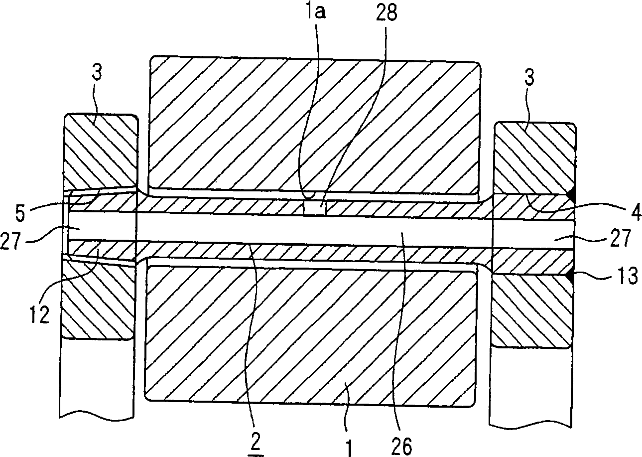
[0076] The annular side plates 3, 3 are arranged oppositely, and the rolling body 1 formed in the shape of a cylindrical roller is placed between the pair of annular side plates, and in the pair of annular side plates 3, the figure 2 An annular side plate 3 on the left side is formed with a plurality of threaded holes 5, wherein the plurality of threaded holes ...


PUM

PropertyMeasurementUnit
Surface roughnessaaaaaaaaaa

Abstract

The ends of the pins (2) rotatably supporting the rolling bodies (1) are fitted in pin receiving holes (4) in the annular side plates (3). The interference between the pin receiving hole (4) and the outer diameter of the pin (2) is in the range of 5 to 40 μm. The end of the pin (2) is welded to the annular side plate (3), wherein the end of the pin (2) is pressed into the pin receiving hole (4) with an interference of 5-40 μm.

Description

technical field [0001] The present invention relates to a cage used in a roller bearing, such as a cylindrical roller bearing or a tapered roller bearing, more particularly, it relates to a cage used in a roller bearing, called a pin cage shelf. Background technique [0002] In rolling bearings such as those used in reducers of rolling mills or presses, cylindrical or conical rollers are used as rolling bearings fitted between the outer and inner bearing retaining rings due to repeated sudden fluctuations in the load in the radial direction body. Cages for holding rolling elements of such rolling bearings (hereinafter referred to as "roller bearings") include various types, and those called pin cages are constructed so as to be inserted through rollers ( One end of the pin of the center hole of the rolling body) is fitted into the pin receiving hole, and the annular side plate and the pin are welded so as to cover the entire end surface of the pin (which fits into the pin ...

Claims


Application Information

Patent Timeline
IPC IPC(8): F16C33/52F16C19/26F16C43/04
Inventor 大高一彦采谷殉一城崎喜彦佐藤幸夫山本高志铃木佑
Owner NSK LTD
Why Eureka
Try Eureka