Supercharge Your Innovation With Domain-Expert AI Agents!

Exhaust structure for engine

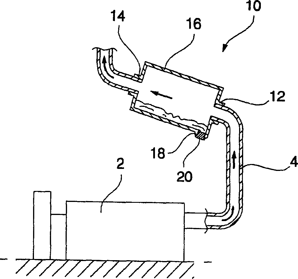
一种引擎、排气管的技术,应用在排气装置、机器/发动机、机械设备等方向,能够解决不可能清除废气排出管路4冷凝水、引擎2损坏等问题,达到防止引擎损坏、提高寿命和可靠性的效果

Inactive Publication Date: 2006-06-14
LG ELECTRONICS INC
View PDF0 Cites 8 Cited by
  • Summary
  • Abstract
  • Description
  • Claims
  • Application Information

AI Technical Summary

Problems solved by technology

[0013] However, in the above-mentioned conventional exhaust structure, it is impossible to remove the condensed water generated in the exhaust gas discharge line 4
For this reason, there is a problem that condensed water can flow back into the engine 2, causing damage to the engine 2

Method used


Image

  • Exhaust structure for engine
  • Exhaust structure for engine
  • Exhaust structure for engine

Examples


Embodiment Construction

[0033] Exemplary embodiments of the combined heat and power system according to the present invention will be described below with reference to the accompanying drawings.

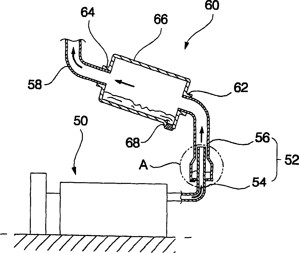
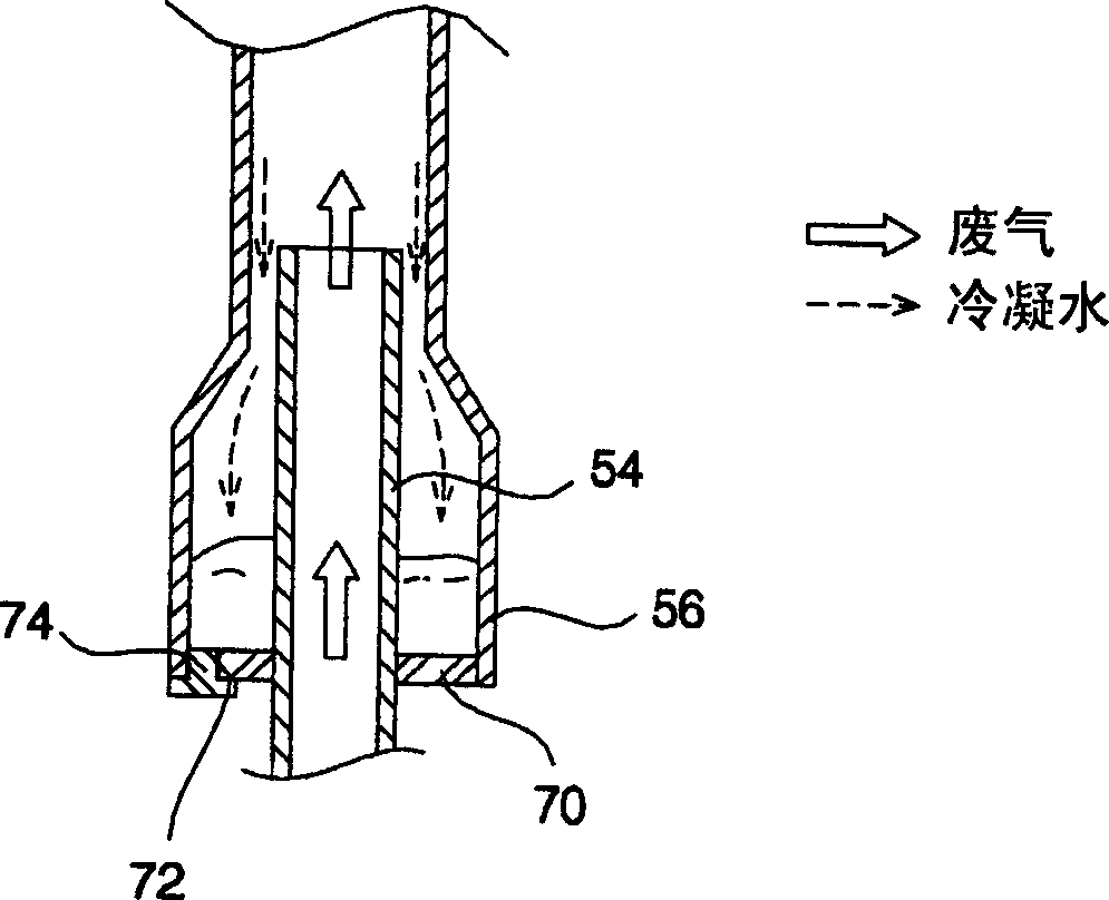
[0034] figure 2 is a schematic diagram showing an exhaust structure for an engine according to a first embodiment of the present invention. image 3 for corresponding to figure 2 An enlarged cross-sectional view of part A.

[0035] Such as figure 2 and image 3 As shown, the exhaust structure according to the first embodiment of the present invention is used to discharge the exhaust gas generated from the engine 50 to the outside, the exhaust structure includes an exhaust gas discharge pipe for discharging the exhaust gas generated from the engine 50 to the outside Road 52.

[0036] The exhaust gas discharge line 52 includes: a first exhaust pipe 54 connected to the engine 50 to guide exhaust gas discharged from the engine 50; and a second exhaust pipe 56 connected to the first exhaust pipe 54 to gu...


PUM


Abstract

An exhaust structure for an engine includes an exhaust line, through which exhaust gas discharged from the engine passes. The exhaust line includes a pipe structure capable of preventing the condensed water formed in the exhaust line from entering the engine, so that it is possible to prevent engine failure, and thus, to achieve an enhancement in the durability and reliability of the engine.

Description

technical field [0001] The present invention relates to an exhaust structure for an engine, in particular to an exhaust structure for an engine, wherein the exhaust pipeline through which the exhaust gas discharged from the engine passes has a sleeve structure to prevent the Condensate formed in the engine can enter the engine, which can improve the life and reliability of the engine. Background technique [0002] Generally, cogeneration systems are adapted to generate electricity and heat from a single energy source. [0003] Such a combined heat and power system can recover waste heat from cooling water or exhaust gas heat generated by the engine or steam turbine during power generation operation, thus enabling the combined heat and power system to increase energy efficiency by 70-80% compared to other systems. Because of such advantages, combined heat and power systems have recently been receiving high attention as a source of electricity and heat supply for buildings. ...

Claims


Application Information

Patent Timeline
Patent Type & Authority Applications(China)
IPC IPC(8): F01N7/08F01N13/08
CPCF01N3/005Y02T10/20Y02T10/12F01N13/00F01N3/038
Inventor 姜胜晫崔昶民崔源宰林亨洙黄尹提
Owner LG ELECTRONICS INC
Features
  • R&D
  • Intellectual Property
  • Life Sciences
  • Materials
  • Tech Scout
  • Unparalleled Data Quality
  • Higher Quality Content
  • 60% Fewer Hallucinations
Learn More