Flash grating digital micro lens display system

A technology of blazed gratings and digital micromirrors, applied in the direction of diffraction gratings, optics, optical elements, etc., can solve the problems that display technology has not been popularized in a wide range, and achieve bright color expression, wide reproduction area, and color reproduction effect superior effect

Inactive Publication Date: 2006-06-14
YUNNAN ZHIHAI PHOTOELECTRIC TECH
View PDF3 Cites 6 Cited by
  • Summary
  • Abstract
  • Description
  • Claims
  • Application Information

AI Technical Summary

Problems solved by technology

[0017] The above technologies have proposed a solution to improve GLV. However, the display technology based on the principle of diffraction has not been widely popularized so far.

Method used


Image

  • Flash grating digital micro lens display system
  • Flash grating digital micro lens display system
  • Flash grating digital micro lens display system

Examples


Embodiment Construction

[0039] The preferred embodiment of the blazed grating digital micromirror display system is described in detail as follows:

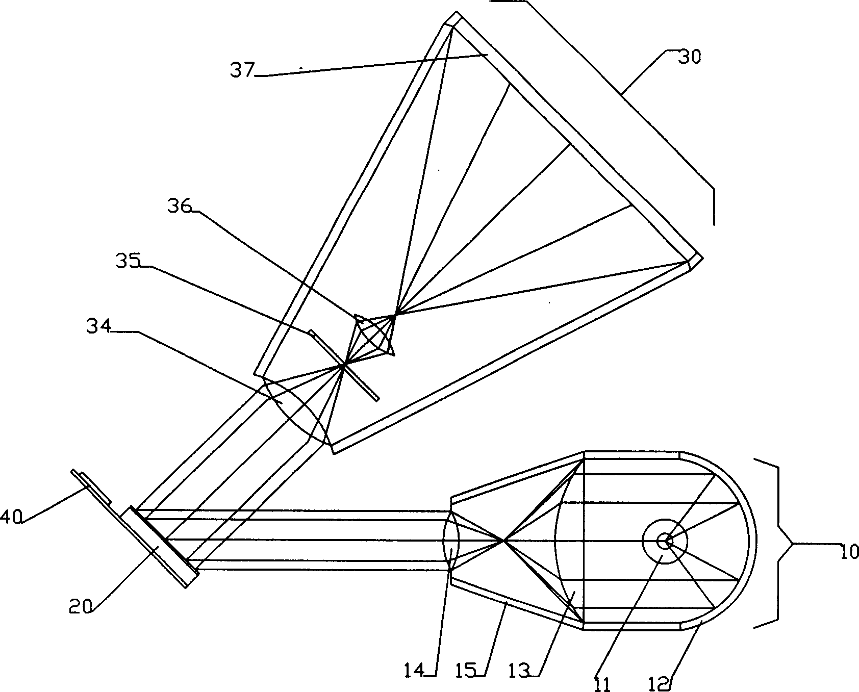
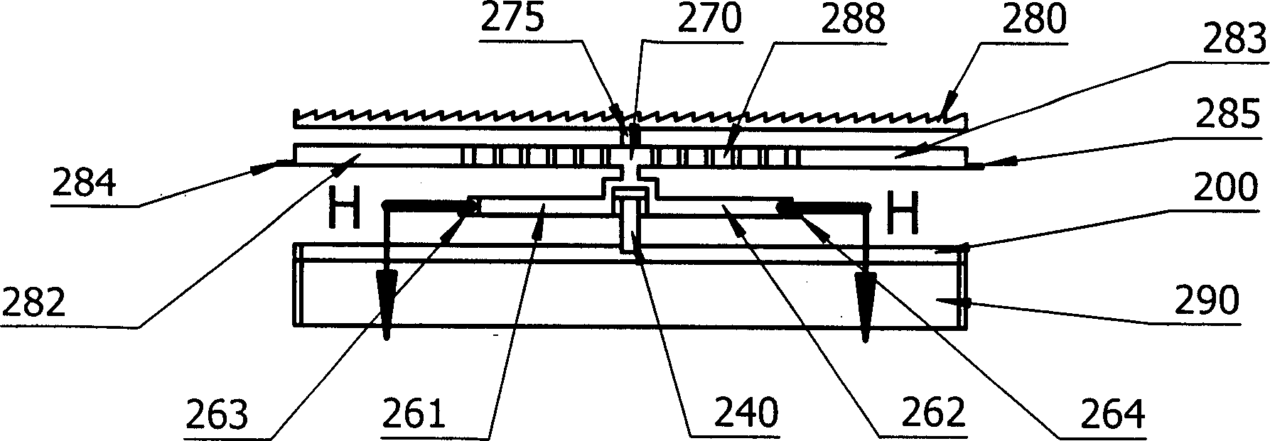
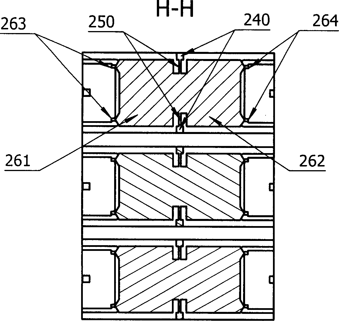
[0040] System Imaging: see figure 1 A blazed grating digital micromirror display system includes an illumination component 10 , a blazed grating digital micromirror 20 , an imaging lens component 30 , and a blazed grating digital micromirror driving component 40 . The illuminating light emitted by the light source 11 is reflected by the reflector 12, focused by the converging lens 13, collimated by the collimator lens 14, and irradiated on the array of blazed grating digital micromirrors 20 at a specific angle of 44.8 degrees. The blazed grating digital micromirror drive components 40 drives the sub-pixels in each pixel of the blazed grating digital micromirror 20 according to the image signal; referring to FIG. An electric field is applied to the electrode 213 and the black photoelectrode 214. Under the action of the electric field force, the blazed g...


PUM


Abstract

The invention relates to a display system based on flaming grating digital microscope that includes lighting component, imaging lens, and driving components. The feature is that the microscope is flaming grating digital microscope that each pixel is made up from three sub-pixels. Comparing to the traditional microscope, the display system could supply higher resolution and brighter color. It has not only high light use factor, but also conquers the disadvantage brought by field sequence lighting. It could be used not only large scale projection TV, but also suit for micro projection display. Especially, it could use sunlight as illuminated light sources.

Description

technical field [0001] The invention relates to micro-displays and projection displays in micro-electro-mechanical systems (Micro Electr-Mechanical System) MEMS, in particular to a blazed grating digital micro-mirror display system. Background technique [0002] Since the invention of display technology, it has basically developed along two roads: pixel units actively emit light to form a picture and pixel units passively emit light to form a picture. [0003] In the active light-emitting mode of the pixel unit, cathode ray CRT display technology first appeared, followed by plasma flat panel PDP display technology, surface conduction emission SED display technology, carbon nanotube field emission CNT display technology, organic electroluminescent diode OLED display technology. [0004] In the display technology in which the pixel unit passively emits light to form a picture, the liquid crystal LCD display technology that realizes display by controlling the degree of light t...

Claims


Application Information

Patent Timeline
Patent Type & Authority Applications(China)
IPC IPC(8): G02B27/00G02B5/18G09F9/30
Inventor 赵捷
Owner YUNNAN ZHIHAI PHOTOELECTRIC TECH
Why Eureka
Try Eureka