Plane luminous display of lowergrid structure and mfg. tech. thereof

A light-emitting display and lower gate technology, applied in the field of nanoscience, can solve the problems of relatively high requirements for insulating materials, inability to perform large-area production, and increase in the overall cost of devices, so as to reduce the probability of intercepting electrons, improve the success rate, and reduce damage. Effect

Inactive Publication Date: 2006-06-14
ZHONGYUAN ENGINEERING COLLEGE
View PDF0 Cites 2 Cited by
  • Summary
  • Abstract
  • Description
  • Claims
  • Application Information

AI Technical Summary

Problems solved by technology

At present, most of the flat-panel displays have chosen the structure type in which the control grid is located above the carbon nanotube cathode, which has the characteristics of simple manufacturing structure, strong control function, and simplified manufacturing process, but the formed grid current is relatively large. The requirements for the insulating material of the device are relatively high, and because the materials for making the control gate are different, some special manufacturing processes are used, resulting in an increase in the overall cost of the device and the inability to make large-area production. These are its disadvantages

Method used


Image

  • Plane luminous display of lowergrid structure and mfg. tech. thereof
  • Plane luminous display of lowergrid structure and mfg. tech. thereof
  • Plane luminous display of lowergrid structure and mfg. tech. thereof

Examples


Embodiment Construction

[0043] The present invention will be further described below in conjunction with accompanying drawing and embodiment, but the present invention is not limited to these

[0044] Example.

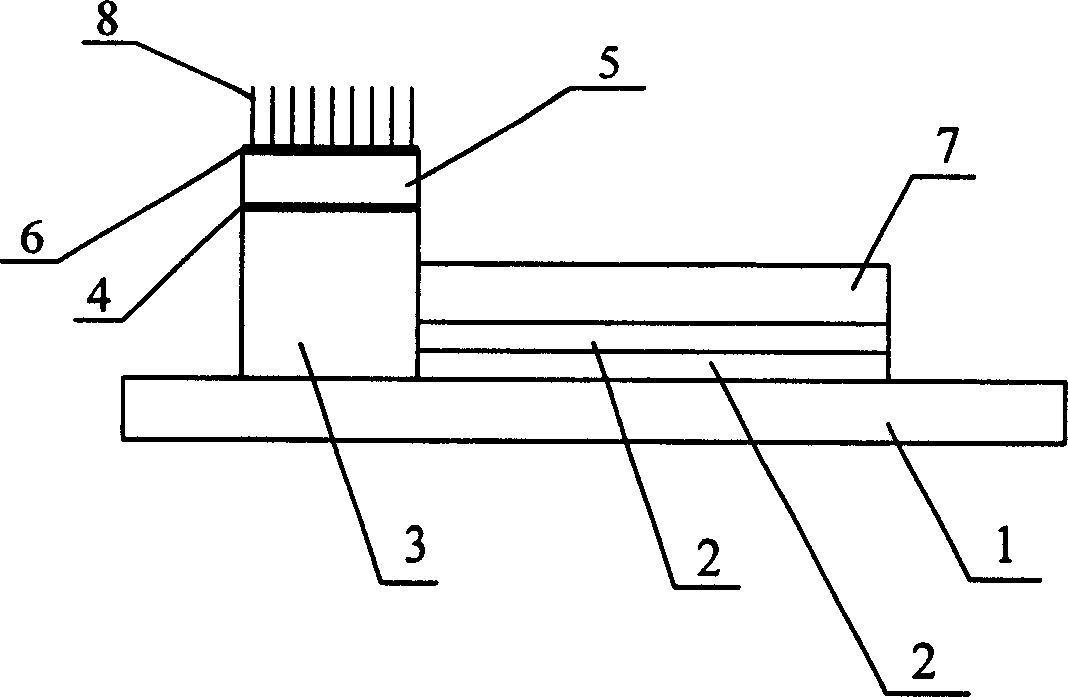
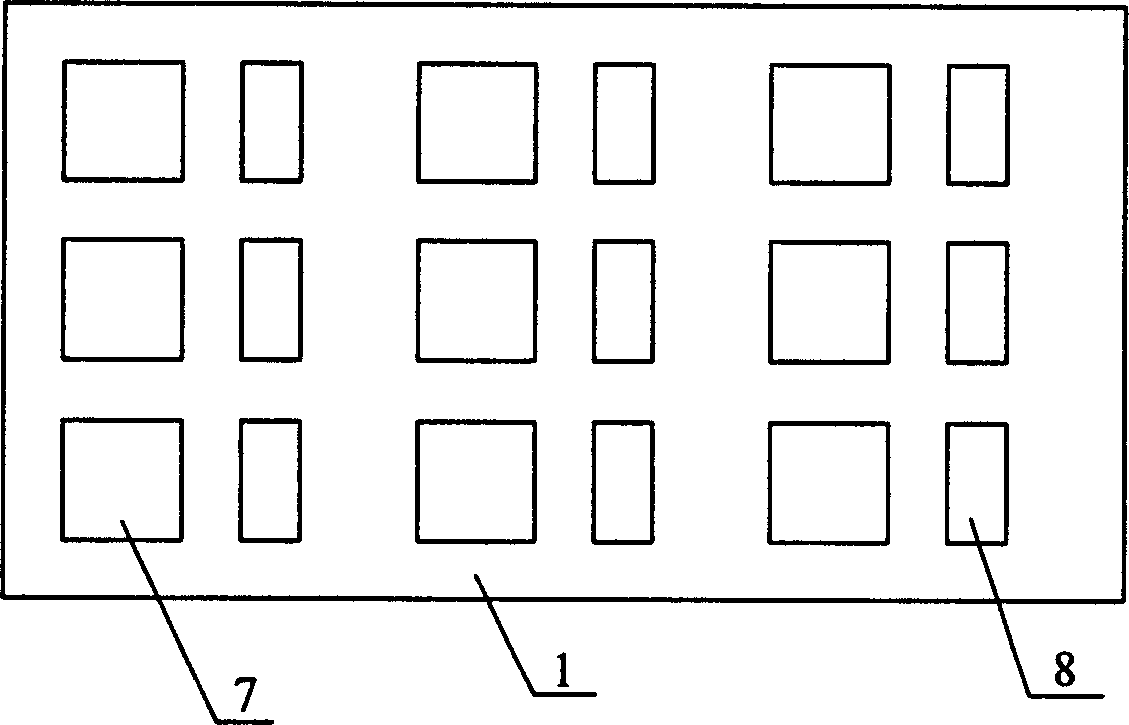
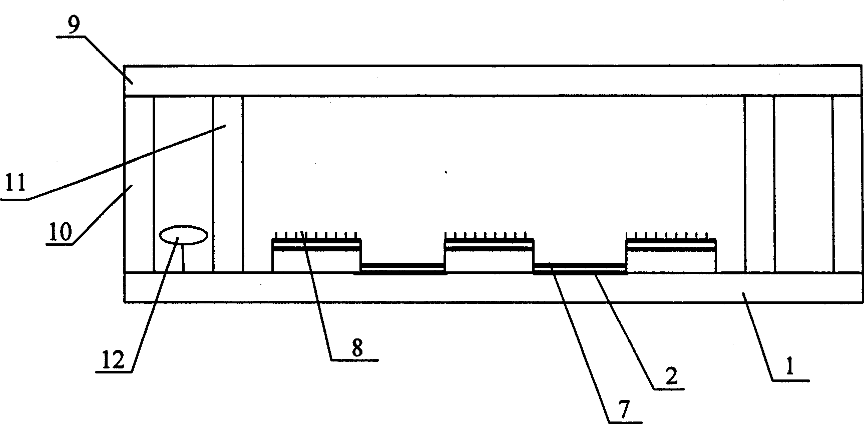
[0045] The present invention includes a sealed vacuum chamber composed of a front glass panel 9, a rear glass panel 1 and surrounding glass frames 10, a supporting wall structure 11 and an attached getter 12 element, and an insulating layer 3 is arranged on the rear glass panel. An anode pixel hole is reserved on the insulation enhancement layer 3, and in the anode pixel hole is an anode electrode layer 2 arranged on the rear glass panel 1, and a phosphor layer 7 is arranged on the anode electrode layer 2, and on the insulation enhancement layer 3 A control grid electrode layer 4 is provided, an insulating isolation layer 5 is arranged on the control grid electrode layer 4, a cathode electrode layer 6 is arranged on the insulation isolation layer 5, and a carbon nanotube cathode 8 is prepared...


PUM


Abstract

The invention relates to a lower grid-structured flat light-emitting display and the making process thereof, comprising a sealed vacuum cavity composed of a front glass panel, a rear glass panel and glass frames, a supporting wall structure and auxiliary degassing agent components. The rear glass panel is provided with an insulating heightening layer, anode pixel holes are preset on the insulating heightening layer, an anode electrode layer is arranged in the anode pixel holes, a fluorescent powder layer is arranged on the anode electrode layer, a control grid electrode layer is arranged on the insulating heightening layer, an insulating isolating layer is arranged on the control grid electrode layer, a cathode electrode layer is arranged on the insulating isolating layer and carbon nanotube cathodes are prepared on the cathode electrode layer. The invention has the advantages of low cost, simple structure, high making yield, stable and reliable lower grid structure.

Description

technical field [0001] The invention belongs to the intercrossing fields of nanometer science and technology, flat panel display technology and vacuum science and technology, and relates to the production of flat field emission light-emitting display devices, and specifically relates to the content of the device production of flat field emission display devices of carbon nanotube cathodes The invention relates in particular to a manufacturing process of a field emission flat display device with a lower gate structure and a carbon nanotube cathode. Background technique [0002] For the most part, people rely on some form of display to communicate with their computer systems. Flat-panel displays are the fundamental display component of devices ranging from the dashboard indicator dials of cars to the high-definition displays of high-end laptops. Compared with ordinary CRT monitors, flat panel monitors have many advantages, such as small footprint, thinness, high image display...

Claims


Application Information

Patent Timeline
Patent Type & Authority Applications(China)
IPC IPC(8): H01J9/00H01J17/04H01J17/16H01J17/49
Inventor 李玉魁
Owner ZHONGYUAN ENGINEERING COLLEGE
Why Eureka
Try Eureka