

Slit type ladle bottom blowing powder injection process and apparatus
A slit-type, powder-spraying technology, used in the manufacture of converters, etc.
- Summary
- Abstract
- Description
- Claims
- Application Information
AI Technical Summary
Problems solved by technology
Method used
Image

Examples
Embodiment 1
[0121] Embodiment 1 further describes the slit-type ladle bottom blowing powder device of the present invention, and Embodiments 2-6 specifically describe the slit-type ladle bottom blowing powder process implemented under different equipment parameters and different process conditions.
[0122] Example 1
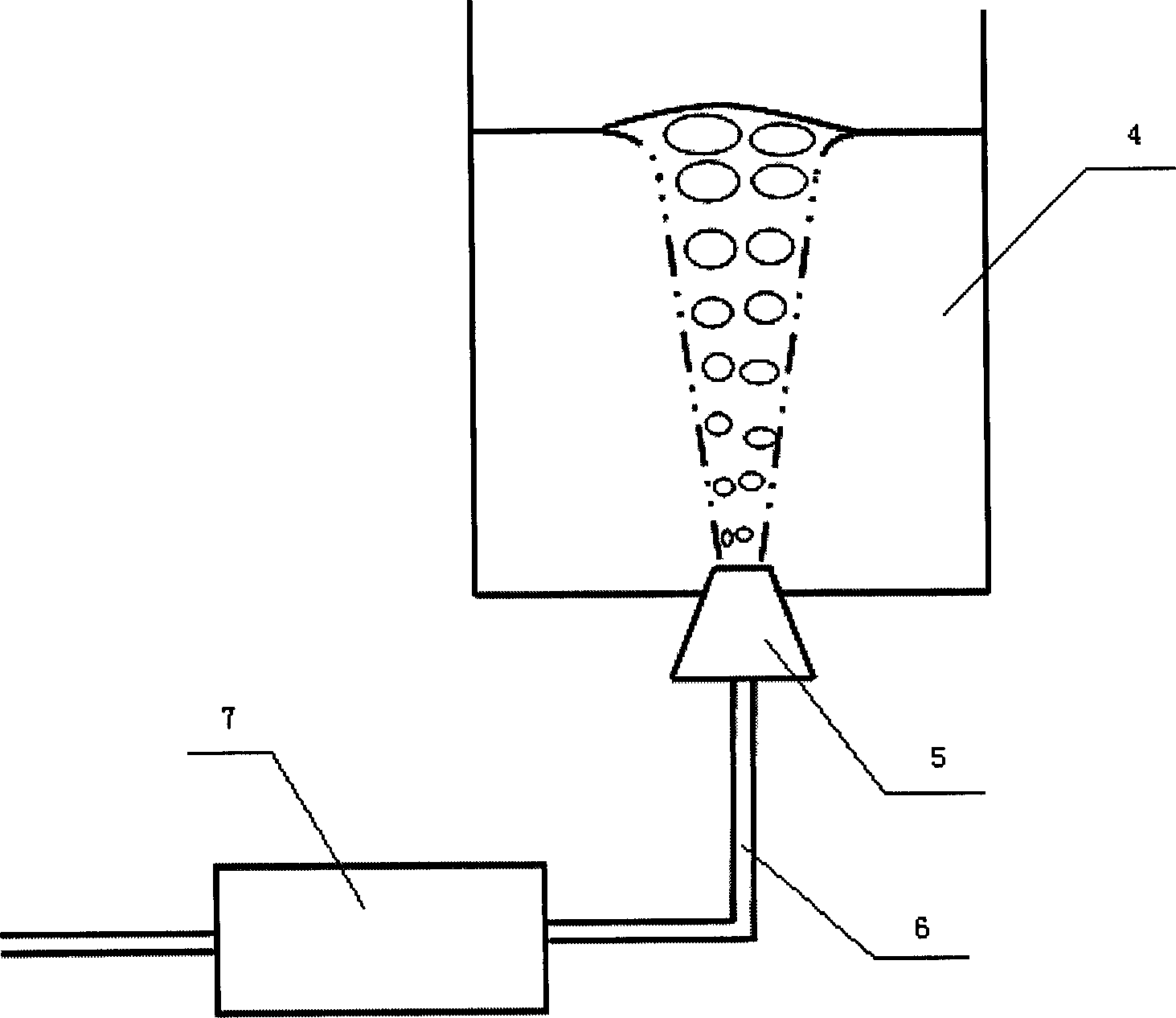
[0123] Such as figure 2 As shown, the slit-type ladle bottom blowing powder spraying device of the present invention includes a slit-type air-permeable brick 5 , a pipeline 6 , and a powder spraying tank system 7 . The slit-type air-permeable brick 5 is installed at the bottom of the ladle 4, and the slit-type air-permeable brick 5 is connected with the powder spray tank system 7 through the pipeline 6.
[0124] There is a slit in the middle of the slit-type air-permeable brick, which is symmetrically distributed, and the slit width should be limited to 0.1mm to 0.3mm.
[0125] The powder spray tank system 7 includes 8 storage bins, 9 manual sliding door, 10 feed valve, ...
Embodiment 2
[0144] Cold state implementation, the implementation conditions are as follows:
[0145] Ventilation bricks: slit-type ventilation bricks used on 30-ton ladles. The outlet diameter of the ventilation bricks is 73mm, the slit width is 0.15mm, and the number of slits is 18.
[0146] Powder: passivated lime, particle diameter less than 45μm
[0147] Delivery gas: compressed air after drying
[0148] The velocity of gas in the pipeline: 10m / s
[0149] Temperature: room temperature
[0150] Contact medium: atmosphere
[0151] Gas pressure: 0.3MPa
[0152] Powder volume percentage: φ=0, 10, 20, 30, 40
[0153] Implementation process: In this embodiment, the gas powder flow is directly injected into the atmosphere. Before powder spraying, the drainage gas is first opened until the predetermined pressure is 0.3MPa, and then the feeding valve is opened to start powder spraying. After the lime injection is completed, the feeding valve is closed. , the drainage gas continues to wor...
Embodiment 3
[0156] For hot implementation, the implementation conditions are as follows:
[0157] Ventilation bricks: slit-type ventilation bricks used on 30-ton ladles, the outlet diameter of the ventilation bricks is 73mm, and the slit width is 0.15mm. In order to be suitable for working on a small induction furnace, the number of slits of the ventilation brick is reduced from 18 to 8.
[0158] Powder: carbon powder, the particle diameter is less than 30μm
[0159] Delivery gas: compressed air after drying
[0160] The velocity of gas in the pipeline: 7m / s
[0161] Temperature: 1500°C
[0162] Contact medium: molten iron
[0163] Gas pressure: 0.45MPa
[0164] Container: 200kg induction furnace
[0165] Powder volume percentage: φ=10, 30
[0166] Implementation process: In this embodiment, carbon powder is sprayed into a 200kg induction furnace equipped with molten iron. Before powder spraying, the drainage gas is first opened until the predetermined pressure of 0.45 MPa is reached...
PUM
| Property | Measurement | Unit |
|---|---|---|
| Diameter | aaaaa | aaaaa |
| Diameter | aaaaa | aaaaa |
| Diameter | aaaaa | aaaaa |
Abstract
Description
Claims
Application Information