Radio relay device

A radio relay and radio communication technology, applied in radio relay systems, active electrical relay systems, radio transmission systems, etc., can solve the problems of complex structures of IF operating systems and RF operating systems, and delays in sending and receiving, reducing Effect of unwanted radiation, improved isolation, the number of lines that can be accommodated, or the effect of increased communication speed

Inactive Publication Date: 2006-06-21
MATSUSHITA ELECTRIC WORKS LTD
View PDF0 Cites 6 Cited by
  • Summary
  • Abstract
  • Description
  • Claims
  • Application Information

AI Technical Summary

Problems solved by technology

[0008] In addition, in the conventional example, when one of the dual-system radio equipment installed in the radio relay device transmits, the other also transmits, and when one receives, the other also receives. In the above-mentioned conventional example, between the base station and the terminal There is a delay in sending and receiving due to the time reversal of sending and receiving between when communicating with a radio relay device and when not using a radio relay device.
[0009] F

Method used


Image

  • Radio relay device
  • Radio relay device
  • Radio relay device

Examples


Embodiment approach 1

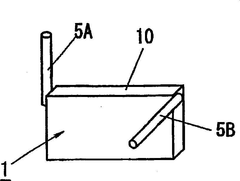
[0050] figure 1 The appearance of the radio relay device 1 according to the present embodiment is shown, and it is characterized in that the inside of the device main body 10 and Figure 17 The radio relay device 1 shown is the same, storing dual-system radio equipment parts (not shown), and installing a monopole-type antenna 5A facing the base station and a monopole-type antenna 5A facing the terminal on both sides of the device body 4, respectively. Antenna 5B is used as the antenna device of radio repeater 1, and the antenna 5A facing the base station is connected with the antenna feeding circuit facing the radio equipment part of the base station, and the antenna 5B facing the terminal is connected with the antenna 5B facing the terminal. Connect to the antenna feed circuit of the radio equipment section of the machine.

[0051] Furthermore, in the illustrated example, the polarization surface of the antenna 5A facing the base station is oriented vertically, and the polar...

Embodiment approach 2

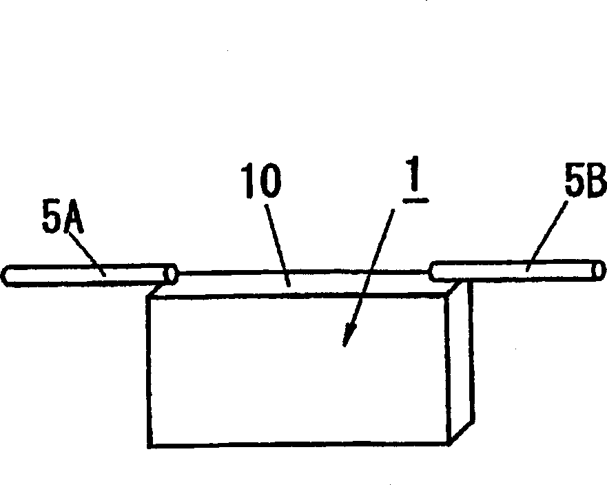
[0056] In Embodiment 1, although an antenna device is used in which the polarization plane of the antenna 5A facing the base station and the polarization plane of the antenna 5B facing the terminal are different, the present embodiment is characterized in that, as figure 2 Shown is an antenna device configured with a monopole-type base station-facing antenna 5A and a terminal-facing antenna 5B disposed on both sides of the upper surface of the main body 10 of the device. They are arranged horizontally toward each other in the null direction.

[0057] Thus, in this embodiment, by orienting the antenna 5A facing the base station and the antenna 5B facing the terminal towards the null direction, the isolation between the antennas 5A and 5B can be improved and the receiving sensitivity due to self-interference waves can be reduced. Inhibition, so that the accommodated line or communication speed of each radio relay device is increased.

[0058] Also, in the device main body 10 a...

Embodiment approach 3

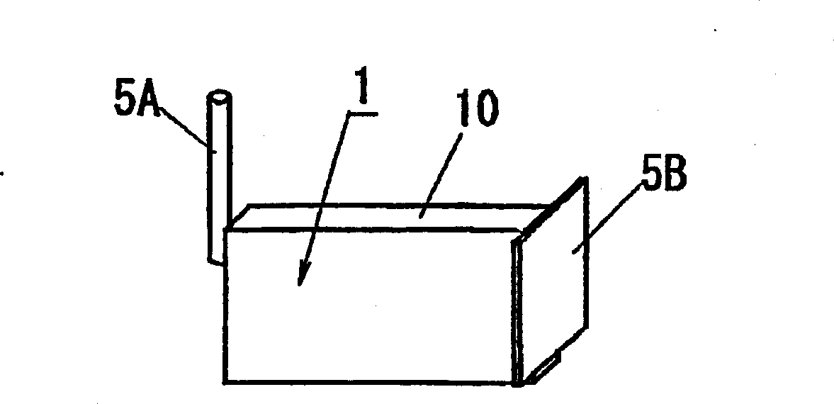
[0060] This embodiment is characterized in that, as image 3 An antenna device composed of an antenna 5A facing a base station and an antenna 5B facing a terminal is used as shown, and the antenna 5A facing a base station is arranged in a vertical direction on one side of the device main body 10 of the radio relay device 1 and is non-directional. Dipole type, the antenna 5B facing the terminal is composed of a chip antenna arranged on the other side of the device main body 10 and has directivity.

[0061] Thus, in this embodiment, by setting the antenna 5A facing the base station as a non-directional antenna and the antenna 5B facing the terminal as a directional antenna, it is possible to maintain and use the non-directional antenna for the two antennas 5A, 5B. The same relayable area of ​​the radio relay device, and in this state, the isolation between the antennas 5A and 5B is improved, and the suppression of receiving sensitivity caused by its own interference wave is redu...


PUM


Abstract

A radio relay device, which is used in the following radio communication system and is equipped with an antenna device, the antenna device has an antenna facing a base station and an antenna facing a terminal, and is used for transmitting between the base station and the terminal and receiving radio waves, the above-mentioned radio communication system adopts the TDMA method in which the frequency bands used in the transmission channel and the reception channel are close to each other, and the above-mentioned antenna device makes the direction of the polarization plane of the antenna facing the base station and the direction of the polarization plane of the antenna facing the terminal different settings.

Description

technical field [0001] The present invention relates to a radio relay device used in a radio communication system using a TDMA method in which frequency bands used for a transmission channel and a reception channel are adjacent to each other for compensating for a weak electric field area as a communication area. Background technique [0002] When radio waves are relayed in a radio communication system adopting TDMA (Time Division Multiple Access) mode, it is necessary to use a TDMA radio relay device 1 such as Figure 17 As shown, dual-system radio equipment units 2A and 2B are installed, and one radio equipment unit 2A communicates with the base station 3 , while the other radio equipment unit 2B communicates with the terminal 4 . At this time, for example, the demodulated signal received and demodulated by the reception unit (not shown) of the radio equipment unit 2A from the base station 3 through the antenna 5A facing the base station is sent to the transmission unit (no...

Claims


Application Information

Patent Timeline
IPC IPC(8): H01Q3/24H04B7/15H01Q1/24H04B7/10H04B7/155H04B7/26
CPCH04B7/1555H04B7/10H04B7/15571
Inventor 栗田昌典新居隆之松本一弘松尾昌行
Owner MATSUSHITA ELECTRIC WORKS LTD
Why Eureka
Try Eureka