
Bias circuit for direct modulated laser

A bias circuit, laser technology, applied in lasers, laser parts, semiconductor lasers, etc., to reduce implementation costs, increase stability, and design simple and efficient effects

Inactive Publication Date: 2006-07-05
STATE GRID TIANJIN ELECTRIC POWER
View PDF0 Cites 10 Cited by
  • Summary
  • Abstract
  • Description
  • Claims
  • Application Information

AI Technical Summary

Problems solved by technology

In the existing technical literature and patents on the design of the direct modulation laser APC circuit, none of them involves the design of the bias circuit between the direct modulation laser and the driver powered by the positive power supply.

Method used

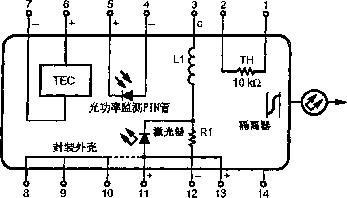
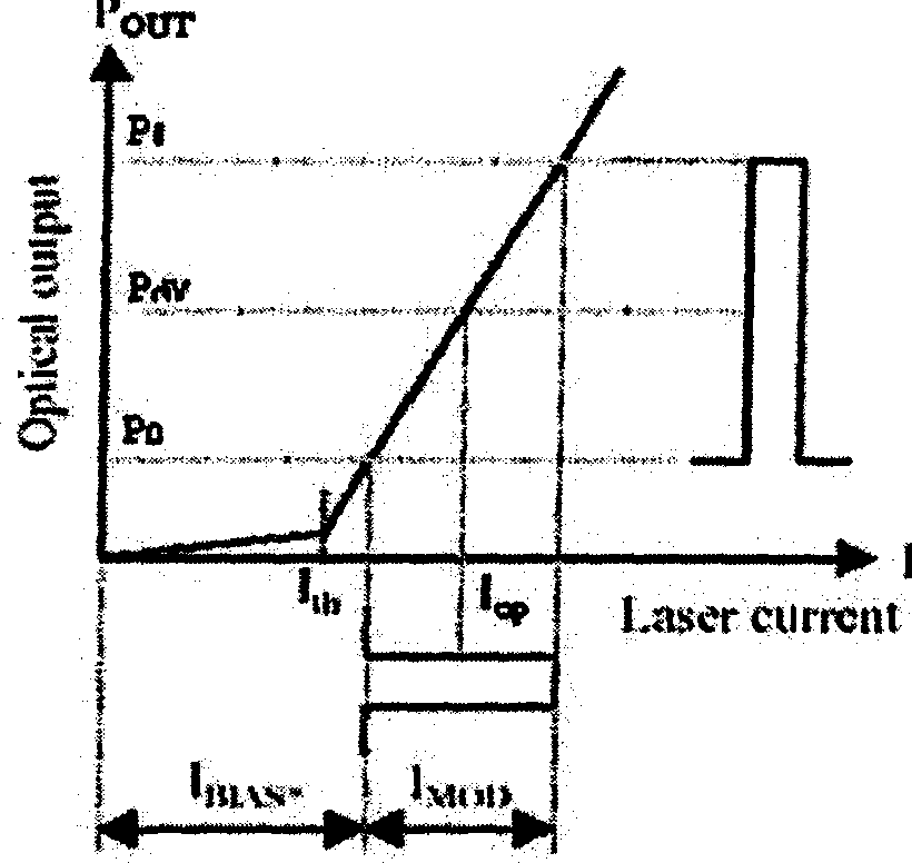
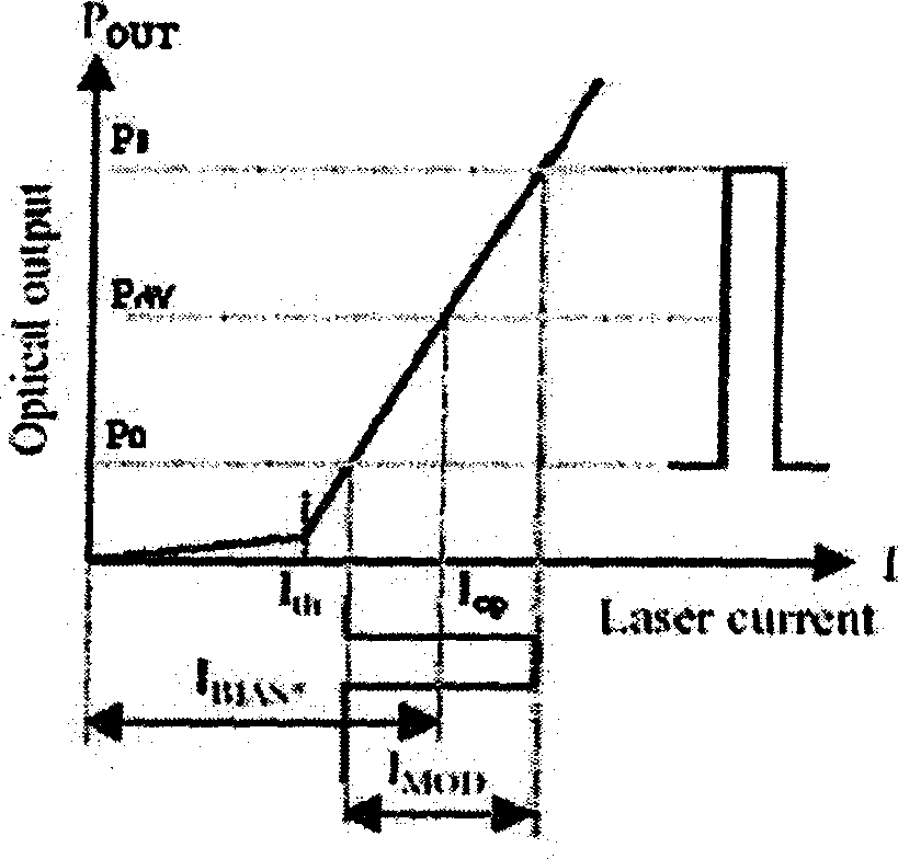

Image

  • Bias circuit for direct modulated laser
  • Bias circuit for direct modulated laser
  • Bias circuit for direct modulated laser

Examples


Embodiment Construction

[0028] Specific preferred embodiments of the present invention will be described in detail below in conjunction with the accompanying drawings.

[0029] The direct modulation laser bias circuit of the present invention, its core technology is to design a triode drive circuit between the driver of the optical transmission module powered by a positive power supply and the direct modulation laser, the triode drive circuit and the laser are converted by a positive and negative power supply The circuit is used to provide a negative power supply; the voltage-controlled current source output of the driver is used to control the base voltage of the triode, thereby controlling the collector current of the triode, and then the collector current is used to drive the laser.

[0030] In the circuit design of the present invention, the resistance voltage divider circuit is cleverly used to realize the control between different power supply circuits, and the driver powered by the positive pow...


PUM


Abstract

Being setup inside optical transmitting module, the bias circuit includes following parts: a laser drive of optical transmitting module of using positive power supplier; a designed triode drive circuit between directive modulated lasers; and a conversion circuit of positive / negative power supply of providing negative power source for triode drive circuit and the said lasers. The output of voltage controlled current source is the input control signal of the triode drive circuit. Current change outputted from voltage-controlled current source of the drive is in use for controlling voltage of base pole in triode, and then current of collector is in use for driving laser to output optical power corresponding to current change. Control loop of automatic control circuit for optical power is formed through drive circuit of triode. Features are: simple and high efficiency, raised stability of module performance, and reduced cost.

Description

technical field [0001] The present invention relates to a direct modulation laser bias circuit applicable to the technical field of digital optical fiber transmission system, in particular to a circuit for realizing direct modulation laser bias current power supply for an optical transmission module in a digital optical fiber communication system or a digital optical fiber network. Background technique [0002] The optical transmission system in the prior art uses a 2.5Gb / s optical transmission module to transmit optical signal services, including STM-16 signals and OC-48 signals, and their rates are 2488.320Mb / s. Usually, the optical transmission module in the WDM optical transmission system uses a large number of cooled direct modulation lasers, which meet the transmission performance requirements of 80Km to 360Km. The laser driver chip and peripheral circuits provide the bias current and modulation current for the direct modulation laser, so as to realize the electrical / o...

Claims


Application Information

Patent Timeline
IPC IPC(8): H04B10/04H01S5/00H04B10/12H04B10/508
Inventor 张赟
Owner STATE GRID TIANJIN ELECTRIC POWER
Learn More