Method for locating interference source in up going route

A technology of interference sources and all directions, applied in transmission monitoring, electrical components, wireless communication and other directions, can solve problems such as low work efficiency, large climate impact, increased interference sources, etc., to reduce workload, improve work efficiency, and reduce skills. desired effect

Active Publication Date: 2006-07-05
张家港信工企业管理咨询有限公司
View PDF0 Cites 31 Cited by
  • Summary
  • Abstract
  • Description
  • Claims
  • Application Information

AI Technical Summary

Problems solved by technology

[0005] 1. Maintenance personnel must go to the site, and the work efficiency is low
Since the beam of the antenna is fixed, the direction angle cannot be adjusted remotely. The whole process must be assisted by maintenance personnel, which is labor-intensive and time-consuming. When building a large-scale station, this method of locating the source of uplink interference is obviously difficult to meet the engineering requirements. progress requirements
[0006] 2. It is greatly affected by the climate
This method requires the maintenance personnel to carry the instrument to the outdoor test. In the case of bad weather, it is inconvenient for the maintenance personnel to travel, which increases the difficulty of finding the source of uplink interference.
[0007] 3. There are certain skill requirements for maintenance personnel
The maintenance personnel must be proficient in using the instrument, and must be able to judge whether the uplink interference may exist according to the test results. Finally, the location of the uplink interference source must be estimated according to the different directions of the uplink interference. Different maintenance personnel may make different decisions due to differences in their own skills. judgment

Method used


Image

  • Method for locating interference source in up going route
  • Method for locating interference source in up going route

Examples


Embodiment Construction

[0029] The present invention will be further described in detail below in conjunction with the accompanying drawings and specific embodiments.

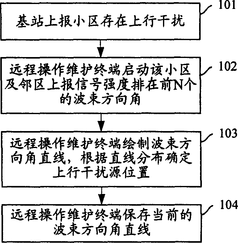
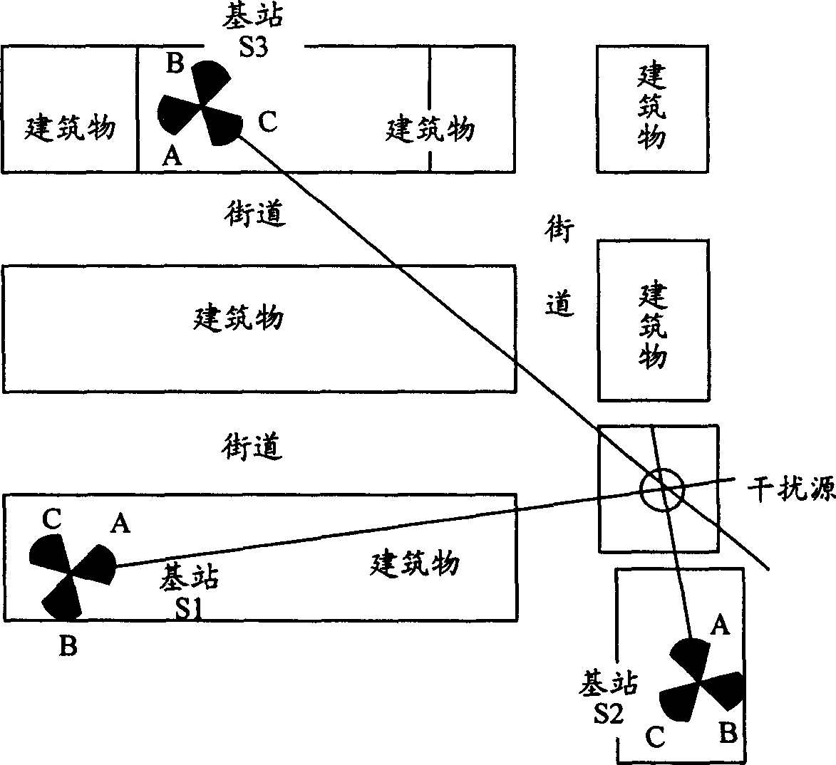
[0030] The present invention locates the uplink interference source firstly through three steps:

[0031] 1. The base station installs a smart antenna system so that the base station supports smart antennas. The so-called smart antenna is an antenna that can be automatically adjusted according to the dynamic signal environment. The beam direction of the antenna can be adjusted according to the strongest uplink signal or interference when receiving and transmitting signals. The smart antenna can increase the directional gain of the antenna, improve the uplink and downlink coverage and capacity of the system through a certain algorithm balance, reduce uplink and downlink multiple access interference, and reduce fading. There are currently two basic types of smart antennas: fixed-beam smart antennas and adaptive smart antennas. The form...


PUM


Abstract

The method includes following steps: when the base station finds there is interference in a cell, and reports it to the remote operation maintaining terminal, the remote operation maintaining terminal locates the upstream interference source base on the direction angle of intelligent antenna beam reported by the cell and its neighboring cells.

Description

technical field [0001] The invention relates to the technical field of signal detection, in particular to a method for locating an uplink interference source. Background technique [0002] In base station design, the uplink signal is required to be within a dynamic range, and demodulation and decoding also have certain requirements on the signal-to-noise ratio of the link. If there are a large number of undesired interference signals in the uplink receiving band, it will affect the quality of the uplink. For wireless systems using power control technology, the transmission power of mobile terminals will be high, thereby reducing the dynamics of base station processing signals. The range threshold reduces the user capacity in the coverage area of ​​the base station, and even some strong interference will directly block the uplink channel, making it impossible or difficult for users to access. Therefore, eliminating uplink interference is of great significance for ensuring th...

Claims


Application Information

Patent Timeline
Patent Type & Authority Applications(China)
IPC IPC(8): H04Q7/34H04B17/00H04W24/04H04B7/02
Inventor 刘鹏
Owner 张家港信工企业管理咨询有限公司
Why Eureka
Try Eureka