Secondary battery
A secondary battery and positive electrode current collector technology, which is applied in the direction of secondary batteries, secondary battery manufacturing, battery electrodes, etc., can solve the problems of large hysteresis, battery discharge voltage drop, and low energy efficiency, so as to prevent short circuits and prevent The effect of contact, high capacity
- Summary
- Abstract
- Description
- Claims
- Application Information
AI Technical Summary
Problems solved by technology
Method used
Image

Examples
no. 1 approach
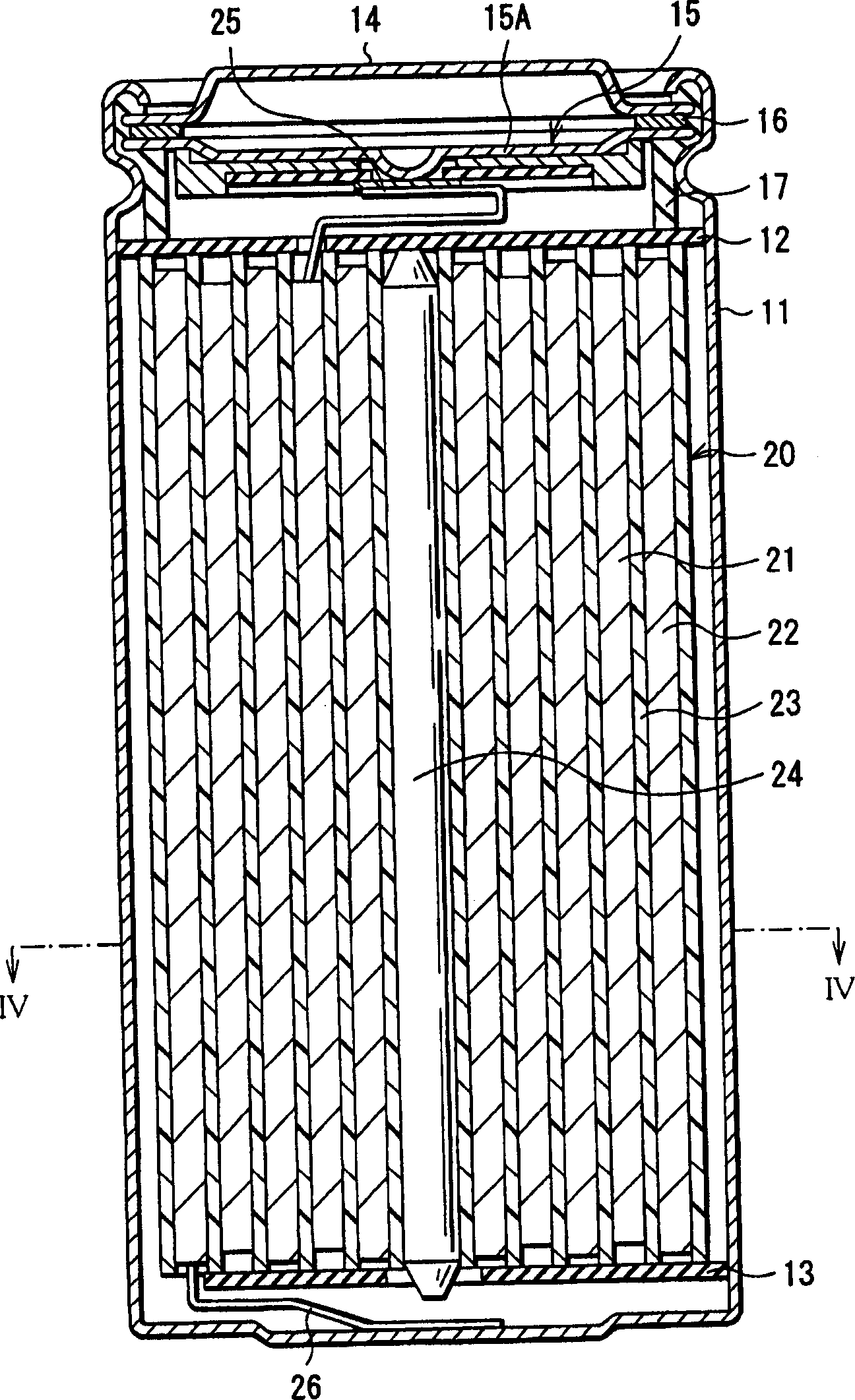
[0047] figure 1 A cross-sectional view of the secondary battery according to the first embodiment of the present invention is shown. This secondary battery is a so-called cylindrical battery, and includes a spirally wound body 20 in a substantially hollow cylindrical battery case 11 . The battery case 11 is made of, for example, iron (Fe) plated with nickel (Ni). One end of the battery is partially closed and the other end is partially open. In the battery case 11 , a pair of insulating plates 12 and 13 are arranged such that the spirally wound body 20 is sandwiched therebetween in a direction perpendicular to the peripheral winding surface.
[0048] In the open end portion of the battery case 11, a battery cover 14, a safety valve mechanism 15 and a positive temperature coefficient device (PTC device) 16 arranged inside the battery cover 14 are installed by caulking through a gasket 17, and the inside of the battery case 11 is sealed. . The battery cover 14 is made of, fo...
no. 2 approach
[0086] Image 6 A cross-sectional view of a spirally wound body 20 according to a second embodiment of the present invention is shown. The spirally wound body 20 has the same structure as that of the first embodiment, except that the exposed positive electrode region 21D is included in the outer end portion 22B1 at a position opposite to the outer end portion 22B1 of the negative electrode active material layer 22B. Except for the protective element 30 on the inner side of the region 21D, and the spirally wound body 20 can be formed in the same manner. Therefore, the same components are denoted by the same numerals as in the first embodiment. Image 6 Diaphragm 23 is not shown.
[0087] In this embodiment, as described above, the exposed positive electrode region 21D includes on the inner side of the exposed positive electrode region 21D at a position opposite to the outer end portion 22B1 of the negative electrode active material layer 22B in the outer end portion 22B1. Pr...
no. 3 approach
[0089] Figure 7 A cross-sectional view of a spirally wound body 20 according to a third embodiment of the present invention is shown. The spirally wound body 20 has the same structure as that of the first embodiment, except that the exposed positive electrode region 21D is included in the outer end portion 22B1 at a position opposite to the outer end portion 22B1 of the negative electrode active material layer 22B. Except for the protective element 30 on the outside and inside of the region 21D, the spirally wound body 20 can be formed in the same manner. Therefore, the same components are denoted by the same numerals as in the first embodiment. Figure 7 Diaphragm 23 is not shown.
[0090] In this embodiment, as described above, the exposed positive electrode region 21D is included on the outer side and the inner side of the exposed positive electrode region 21D at a position opposite to the outer end portion 22B1 of the negative electrode active material layer 22B in a ci...
PUM
| Property | Measurement | Unit |
|---|---|---|
| angle | aaaaa | aaaaa |
| thickness | aaaaa | aaaaa |
| angle | aaaaa | aaaaa |
Abstract
Description
Claims
Application Information
 - R&D
- Intellectual Property
- Life Sciences
- Materials
- Tech Scout
- Unparalleled Data Quality
- Higher Quality Content
- 60% Fewer Hallucinations
Browse by: Latest US Patents, China's latest patents, Technical Efficacy Thesaurus, Application Domain, Technology Topic, Popular Technical Reports.
© 2025 PatSnap. All rights reserved.Legal|Privacy policy|Modern Slavery Act Transparency Statement|Sitemap|About US| Contact US: help@patsnap.com