Video camera reference method only using plane reference object image

A technology for calibrating objects and cameras, which is applied in the field of camera calibration and geometric correction of images, which can solve the problems of difficult to determine the impact and low efficiency, and achieve the effects of improving calibration accuracy, simplifying the calibration process, and improving calibration efficiency

Inactive Publication Date: 2006-07-12
SHANGHAI JIAO TONG UNIV
View PDF0 Cites 16 Cited by
  • Summary
  • Abstract
  • Description
  • Claims
  • Application Information

AI Technical Summary

Problems solved by technology

The disadvantages of this method are: (1) due to the mutual coupling between the distortion coefficient and the internal parameters of the camera, it is possible to obtain a local optimal solution by simultaneously optimizing them; (2) since the calibration result is the result of the joint action of multiple images , it is difficult to determine the impact of one of the images on the calibration result. In order to obtain a better calibration result, it is often necessary to take more images, which is inefficient

Method used


Image

  • Video camera reference method only using plane reference object image
  • Video camera reference method only using plane reference object image
  • Video camera reference method only using plane reference object image

Examples


Embodiment Construction

[0019] In order to better understand the technical solutions of the present invention, a further detailed description will be made below in conjunction with the accompanying drawings and embodiments.

[0020] Camera calibration method of the present invention comprises the following steps:

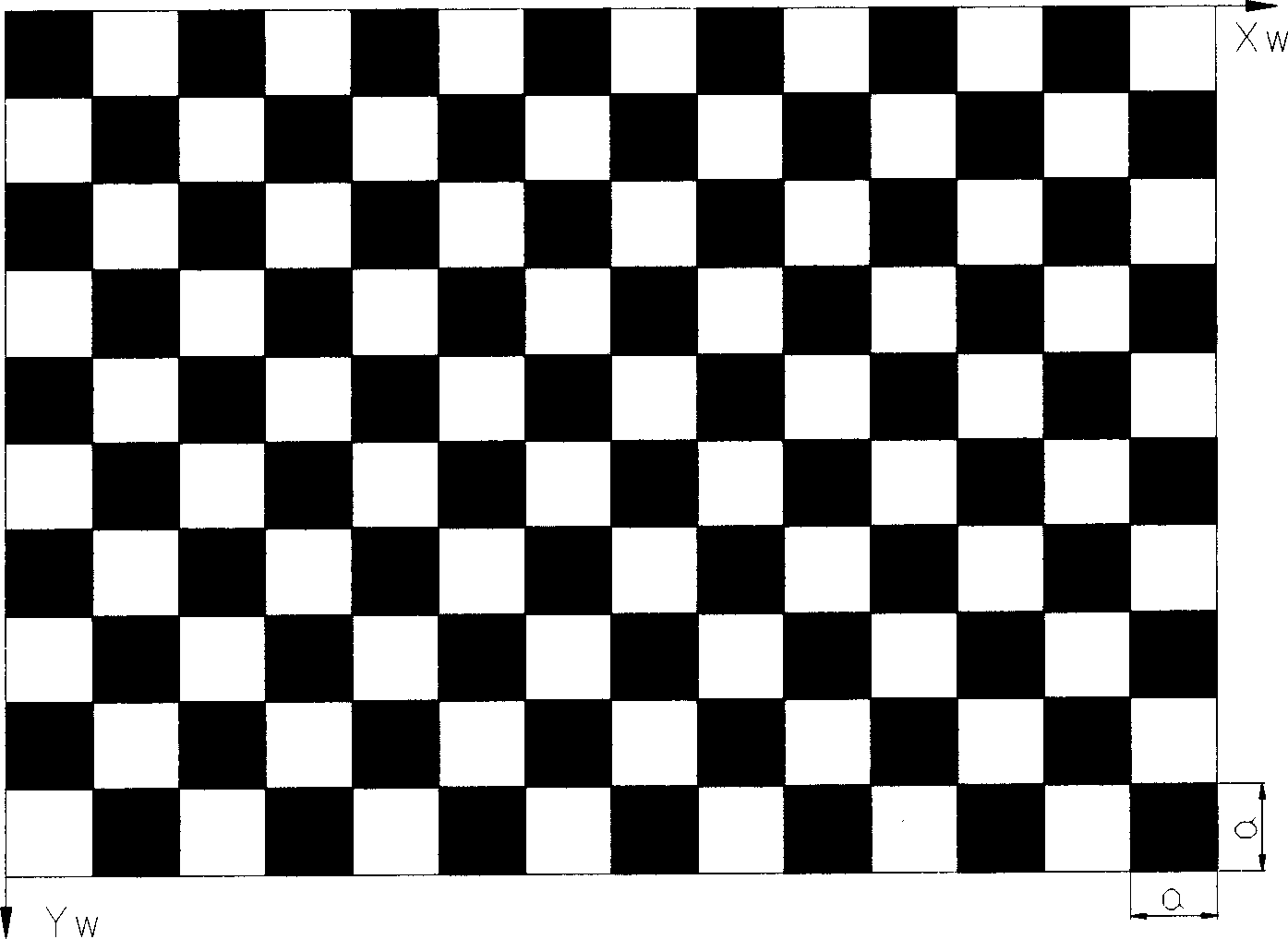
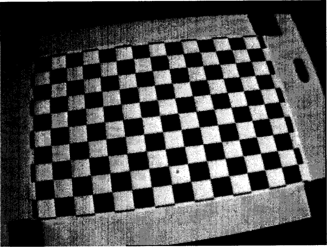
[0021] 1. Set the plane calibration object: Set two sets of parallel straight lines on a plane object as the plane calibration object. The two sets of parallel lines are perpendicular to each other, and the distance between the parallel lines in each group is known, so that the side length is known. flat grid graphics. The side length of the grid pattern changes according to the nominal focal length of different camera lenses. The smaller the nominal focal length, the larger the side length of the square pattern, and vice versa, so that when the image of the plane calibration object is taken, the camera and calibration The distance between objects is within the working range of the actual...


PUM


Abstract

Present invention relates to video camera calibrating method only using one plane calibration object. It contains setting two sets quadrature parallel straight lines given that spacing as calibration object, shooting one image along video camera optical axis with plane calibration object oblique, to make two sets parallel lines approximately in vertical and horizontal two direction of image. Extracting intersecting point in image parallel line and proceeding straight line matching to parallel line, finding out one minimal residuum, using intersecting point of two minimal residuum fitting straight line as principal point initial value, finding out percentage distortion initial value according to residuum with relation, using all fitting straight line residuum sum as objective function, utilizing optimization method proceeding optimization to and percentage distortion, utilizing distortion model removing image distortion, finding out each intersecting point orthoscopic image co-ordinate, finding out video camera whole parameter by linear transformation utilizing intersecting point orthoscopic image co-ordinate and world co-ordinate in plane calibration object, finally to complete calibration.

Description

technical field [0001] The invention relates to a camera calibration method using only one plane calibration object image, which can be applied to camera calibration in computer vision and close-range photogrammetry, and can also be used for geometric correction of images. It belongs to the field of advanced manufacturing and automation. Background technique [0002] Camera calibration has always been an important issue in photogrammetry and computer vision. At present, there are many camera calibration methods. The early camera calibration methods used three-dimensional calibration objects. Due to the difficulty in making three-dimensional calibration objects, they have been gradually replaced by planar calibration objects. With the development of digital camera technology, the current camera model with four internal parameters is sufficient for general applications in computer vision. To calibrate a four-parameter camera model, the prior art of using a planar calibration...

Claims


Application Information

Patent Timeline
Patent Type & Authority Applications(China)
IPC IPC(8): H04N17/00H04N5/225
Inventor 王建华刘允才
Owner SHANGHAI JIAO TONG UNIV
Why Eureka
Try Eureka