Distributing valve for concrete pump

A concrete pump and distribution valve technology, which is applied to the components of the pumping device for elastic fluid, pumps, piston pumps, etc. The effect of local force, better suction performance, and increased use volume

Inactive Publication Date: 2006-07-19
SANY HEAVY IND CO LTD (CN)
View PDF0 Cites 11 Cited by
  • Summary
  • Abstract
  • Description
  • Claims
  • Application Information

AI Technical Summary

Problems solved by technology

The advantage of the gate valve is that the suction port is large, and because there are only stirring blades in the hopper, there is no working device like the S valve, which not only affects the working volume, but also affects the suction performance, so the suction performance of the gate valve is good, especially For concrete with coarse aggregate, the advantages are more obvious; however, due to the working characteristics of the gate valve, the gate valve cannot withstand a large working pressure (generally around 8Mpa), and cannot meet the requirements for high-pressure pumping, while the S valve's The advantage is that the high pressure of the system mainly acts on the inner wall of the circular pipe. When working, the entire pipe wall is evenly subjected to tension and can withstand relatively high pressure. The working pressure can reach 16Mpa or even greater. However, since the S pipe of the S valve is placed in the hopper , occupies a certain volume of the hopper, and at the same time affects the suction of the delivery cylinder

Method used


Image

  • Distributing valve for concrete pump
  • Distributing valve for concrete pump
  • Distributing valve for concrete pump

Examples


Embodiment Construction

[0030] The present invention will be described in further detail below in conjunction with the accompanying drawings and specific embodiments.

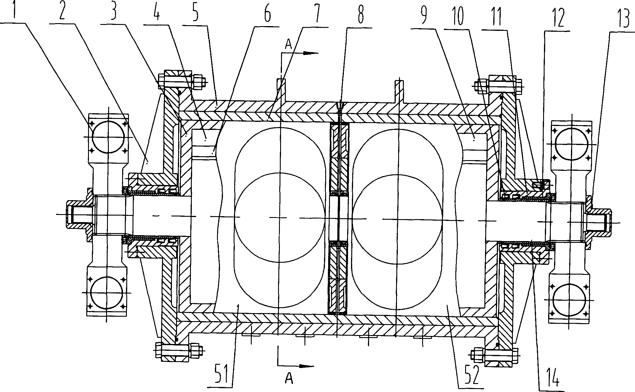
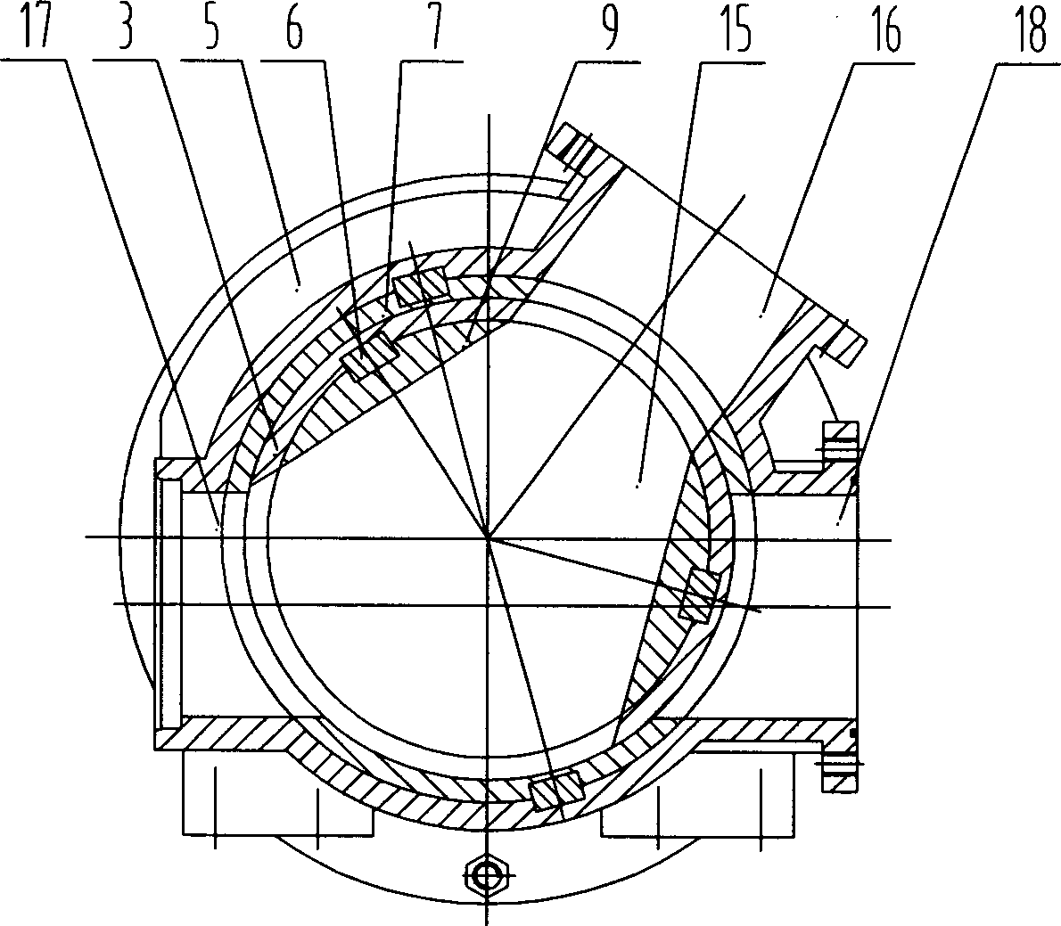
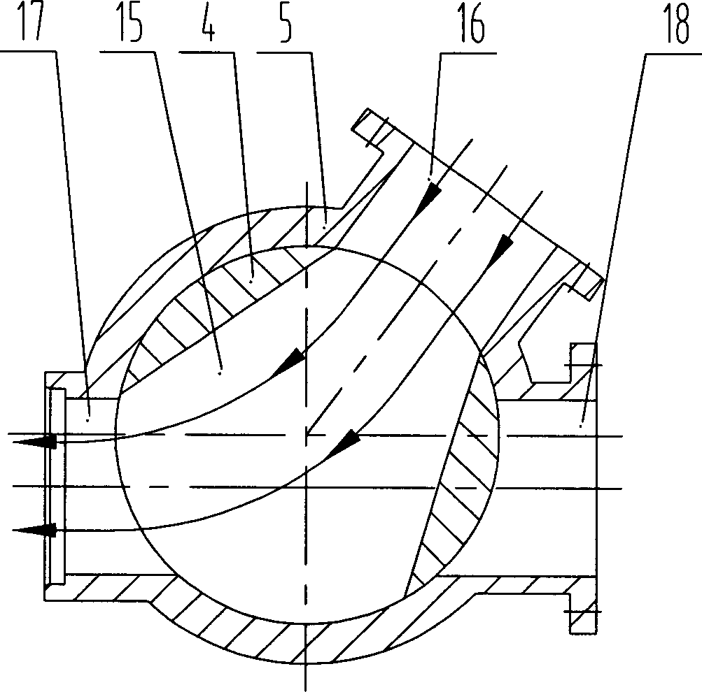
[0031] Such as figure 1 , figure 2 with Image 6 The distribution valve for concrete pump shown in the present invention includes a valve body 5, a rocker arm 1, an end cover 2, a left-turn valve 4 and a right-turn valve 9, and the end cover 2 is installed at both ends of the valve body 5 , divided into left valve cavity 51 and right valve cavity 52 in the cylindrical valve body 5 cavity, the left valve cavity 51 and right valve cavity 52 in the valve body 5 are separated by a spacer 8 or a partition, and the spacer 8 An oil injection channel is opened on the top to inject high-pressure lubricating oil to facilitate the lubrication of the valve body 5 and prevent the infiltration of concrete slurry. A seal is installed on the spacer 8 to prevent the two chambers from colluding; the left-turn valve 4 and right-turn valve 9 can be fl...


PUM


Abstract

The invention discloses a distribution valve of concrete pump, which comprises a valve body, swing arms, two end caps, a left rotational valve and right rotational valve. Wherein, the end caps are arranged at the two ends of valve body; the valve body is divided into left valve chamber and right valve chamber; the left and right rotational valves are individually arranged inside the left and right valve chambers; the parts of valve relative to the left and right valve chambers have inlets, material adsorption inlets and outlets; the left and right rotational valves are individually connected to the swing arms at the outer side of two ends of valve body via the rotational axle; and said left and right rotational valves are cylinder which have through holes to connect the inlet and material adsorption inlet or material adsorption inlet and outlet. The invention has better material adsorption property which can meet the demand of high pressure pump.

Description

technical field [0001] The invention mainly relates to the field of construction machinery, in particular to a distribution valve for a concrete pump. Background technique [0002] With the accelerated development of the national economy, it has greatly promoted the rapid development of my country's construction industry, and high-rise large-scale steel-concrete structures have sprung up. Especially in recent years, with the rapid development and increasing standardization of commercial concrete, more and more It shows the advantages of concrete pumps such as high efficiency, high quality and low consumption, and quickly replaces the traditional and backward concrete pouring method, which has attracted great attention from the construction industry at home and abroad. [0003] At present, in the domestic and foreign markets, there are two main types of concrete pump distribution valves: gate valve and S valve. The advantage of the gate valve is that the suction port is large...

Claims


Application Information

Patent Timeline
Patent Type & Authority Applications(China)
IPC IPC(8): F04B53/10F04B15/02E04G21/02
CPCF04B15/023F04B7/0007F04B7/0011Y10T137/85978
Inventor 易小刚李永维蒋建军
Owner SANY HEAVY IND CO LTD (CN)
Why Eureka
Try Eureka