Apparatus for marking a defect

A defect marking and marking technology, applied in the direction of measuring devices, optical testing flaws/defects, instruments, etc., can solve the problems of product quality reduction, fracture, strength reduction, etc.

Active Publication Date: 2006-07-19
长濑微电子科技有限公司
View PDF6 Cites 39 Cited by
  • Summary
  • Abstract
  • Description
  • Claims
  • Application Information

AI Technical Summary

Problems solved by technology

However, if the sheet-like product is damaged, the strength of this portion will decrease, and accidents such as breakage will easily occur in subsequent processing steps.
In addition, if the chip product is damaged, cutting chips will inevitably be generated. If the cutting chips are mixed into the product, the quality of the product will be reduced. In order to completely remove the generated cutting chips, it is necessary to use a special suction device. Increased costs

Method used


Image

  • Apparatus for marking a defect
  • Apparatus for marking a defect
  • Apparatus for marking a defect

Examples


Embodiment 1

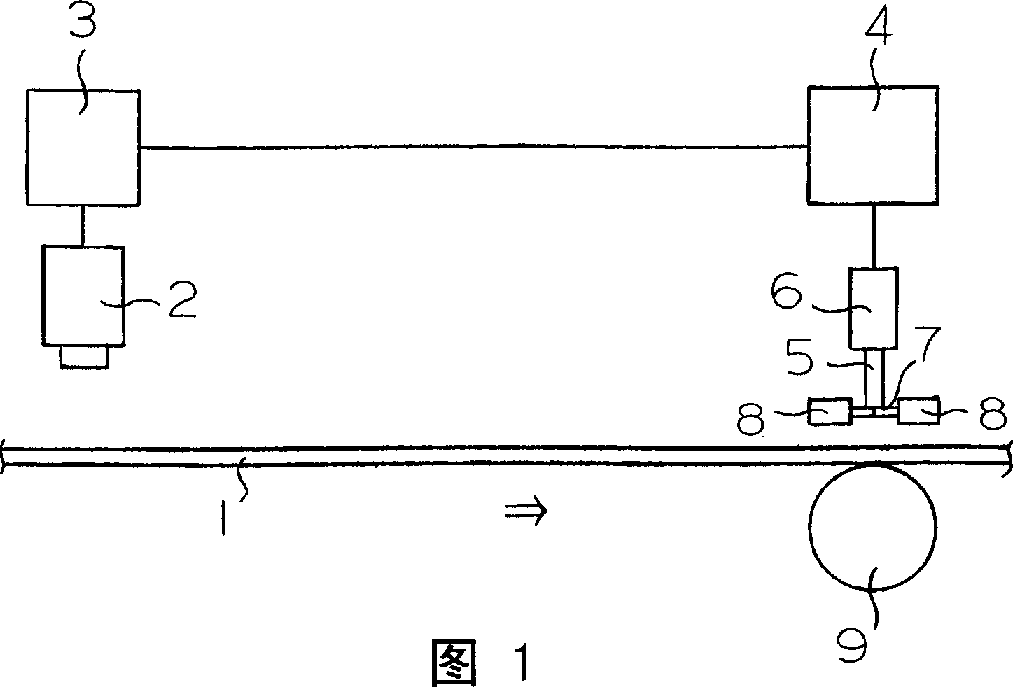
[0165] The inspection was carried out on a biaxially stretched polyethylene terephthalate film having a width of 1600 mm and a thickness of 50 μm. Above the polyethylene terephthalate film, 8 CCD cameras were installed at a pitch of 200 mm, and below the polyethylene terephthalate film, light sources were installed at positions corresponding to the CCD cameras. Above the polyethylene terephthalate film downstream of the CCD camera and the light source 2.0m, a marking head is arranged, and the marking head has 64 groups within a width of 1600mm according to a 25mm pitch, and the marking head will The receiving tube of the oil-based marking pen operated by the solenoid is combined with the shutter of the receiving tube operated by the air cylinder, and a support is provided at the position facing the marking head under the polyethylene terephthalate film. roll.

[0166] The solvent of the ink of oily marking pen is the mixed solvent of the ethanol of 70% by weight and the propy...

Embodiment 2

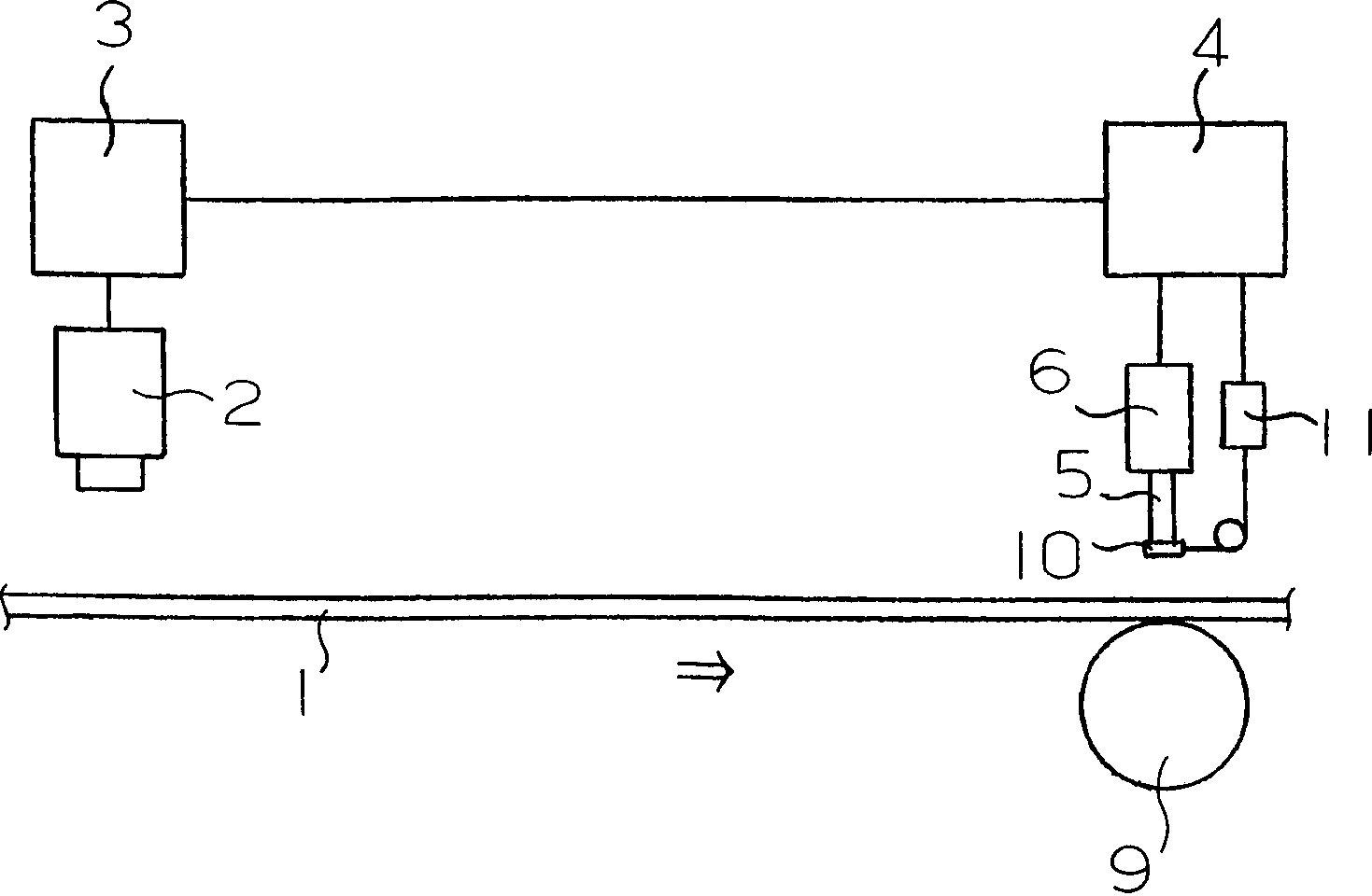
[0169] Inspection was performed on a biaxially stretched polyethylene terephthalate film having a width of 1400 mm and a thickness of 100 μm. Seven CCD cameras were installed at a pitch of 200 mm above the polyethylene terephthalate film, and a light source was installed at a position facing the CCD cameras below the polyethylene terephthalate film. Above the polyethylene terephthalate film downstream of the CCD camera and the light source 2.0m, a marking head is arranged, and the marking head has 70 groups within a width of 1400mm according to a 20mm pitch, and the marking head will The receiving tube of the oil-based marker pen operated by the solenoid is combined with the shutter of the receiving tube operated by the solenoid, under the polyethylene terephthalate film, at the position facing the marking head Set up backup rolls.

[0170] The ink solvent of the oil-based marker pen is ethanol, and the pen tip is made of fiber, and has a cylindrical shape with a diameter of ...

Embodiment B1

[0174]A polycarbonate roll film of a tape carrier for electronic device mounting with a width of 1200 mm and a thickness of 0.2 mm was cut into 60 product films with a width of 20 mm. Six CCD cameras were installed at a pitch of 200 mm above the film, and a light source was installed at a position facing the CCD cameras below the film. A marking device is installed above the film downstream of the CCD camera and the light source 2.0m down. The marking device has 60 groups within a width of 1200mm at a pitch of 20mm. The marking device is an oily marker operated by a solenoid. The assembly of the receiving tube of the pen and the shutter of the receiving tube operated by the air cylinder is provided below the film, on the upstream side of 5 mm from the marking device, and a support roller in contact with the film is provided. An inspection device that processes images taken by a CCD camera to detect defects is connected to a drive device that opens the shutter of an oil marker ...


PUM

PropertyMeasurementUnit
widthaaaaaaaaaa
thicknessaaaaaaaaaa
lengthaaaaaaaaaa

Abstract

An apparatus for marking a defect detects a defect in a long sheet product transferred in a longitudinal direction by an inspection apparatus and places a mark at the defect at a position downstream of the inspection apparatus. An oil-based marking pen is contained in a container tube having a shutter for closing the tip of the pen. The shutter is opened based on a signal sent from the inspectionapparatus, a mark is placed at the defect in the long sheet product by the tip of the pen pushed out of the container tube, the pen is pulled back into the container tube after the marking is completed, and the shutter is closed. The mark can be placed at the portion of the detected defect by an oil-based marking pen without causing a decrease in the marking property due to drying of the tip of the pen.

Description

technical field [0001] The invention relates to a defect marking device. More specifically, the present invention relates to a defect marking device capable of detecting defects of a long sheet-like product conveyed in a lengthwise direction by an inspection device without causing a reduction in marking properties due to drying of the pen tip. , Use an oil-based marker to mark the detected defect. [0002] In addition, the present invention relates to an invention of a form in which a defect marking device using the oil-based marker pen is applied to a specific defect marking device developed by the present inventors. [0003] That is, the present invention also relates to a film cutting device in which, when a roll film is cut and wound, a defect located in the film is detected by an inspection device, and a mark is provided on a defective portion for each cut product film. . [0004] In addition, the present invention relates to a defect marking device capable of detectin...

Claims


Application Information

Patent Timeline
Patent Type & Authority Applications(China)
IPC IPC(8): G01N21/89G03F1/00G01N21/892
Inventor 柴田贤朗
Owner 长濑微电子科技有限公司
Why Eureka
Try Eureka