
Method for capturing and tracing extended beacon for deep space optical communication

A technology of optical communication and laser communication, applied in the direction of position/direction control, re-radiation of electromagnetic waves, utilization of re-radiation, etc., can solve the problems of large error and low precision

Inactive Publication Date: 2006-07-19
HARBIN INST OF TECH
View PDF0 Cites 5 Cited by
  • Summary
  • Abstract
  • Description
  • Claims
  • Application Information

AI Technical Summary

Problems solved by technology

[0004] In order to solve the problems of low precision and large errors when capturing and tracking extended beacons in traditional methods, the present invention provides a method for capturing and tracking extended beacons in deep space optical communication

Method used


Image

  • Method for capturing and tracing extended beacon for deep space optical communication
  • Method for capturing and tracing extended beacon for deep space optical communication
  • Method for capturing and tracing extended beacon for deep space optical communication

Examples


Embodiment Construction

[0025] In this specific embodiment, the natural celestial body earth is used as the extended beacon to be detected, and it is captured and tracked according to the following steps: 1. The position of the earth is captured according to the following steps: 1. in the process of establishing and operating the deep space laser communication link , determine the initial alignment direction of the optical communication terminal in the inertial coordinate system according to the natural celestial body and the aircraft ephemeris, and this direction points to the extended beacon to be captured; ② Convert the aiming direction vector in the above inertial coordinate system to the star In the upper pitch coordinate system, the control of the communication beam is carried out in the on-board pitch coordinate system of the aircraft; ③ According to the relevant technical parameters of the spacecraft, combined with statistical principles to determine the plane field angle of the uncertain regio...


PUM


Abstract

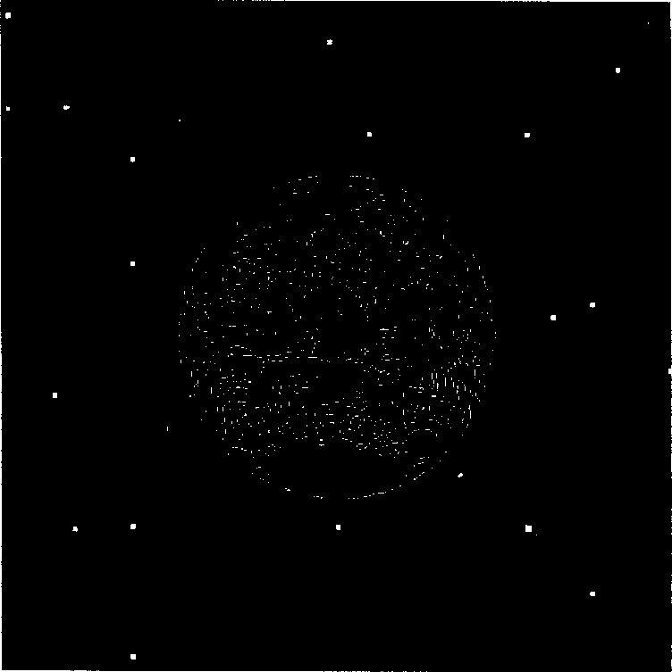
The invention relates to a deep space optical communication expand sighting target capture tracing method, which relates to a processing method of expand sighting target picture. It attaches Gauss white noise on the noise justified approximation of the real sighting target picture and adopts least square method to capture the sighting target picture, ascertains the center location of the sighting target picture, makes the system to enter into the tracing model, and uses dissimilar Fourier transformation method and maximum likelihood method to compute the rotating angle and the moving value of the sighting target picture, then it can compute the center of the sighting target picture by the moving value and the rotating angle and update the optical communication end wire direction by the center location.

Description

technical field [0001] The present invention relates to a method of processing extended beacon images. Background technique [0002] It is the development direction of deep space communication to use laser to transmit scientific data of deep space exploration. The severe challenge of using laser for deep space long-distance information transmission is the precise alignment requirement. The existing deep space optical communication system based on satellite optical communication system design The communication system uses the uplink laser beam launched from the ground as a beacon, but using the uplink laser beam as a beacon not only needs to use a high-power laser, but is also vulnerable to the influence of the atmosphere and the constraints of the weather, which cannot meet the needs of all-weather deep space optical communication links. Therefore, we consider using natural celestial images (visual images or infrared images) as beacons. Since the optical terminal on the air...

Claims


Application Information

Patent Timeline
IPC IPC(8): G01S17/00G05D3/00
Inventor 马晶谭立英徐科华于思源韩琪琪
Owner HARBIN INST OF TECH
Learn More