Wave line winding machine
A technology of wavy wire and winding machine, which is applied in coil manufacturing, non-adjustable metal resistors, electric heating devices, etc., can solve the problems of unwinding heaters and difficult control, and achieve stable and accurate adjustment, uniform and stable forming, and easy distorted effect
- Summary
- Abstract
- Description
- Claims
- Application Information
AI Technical Summary
Problems solved by technology
Method used
Image

Examples
Embodiment 1
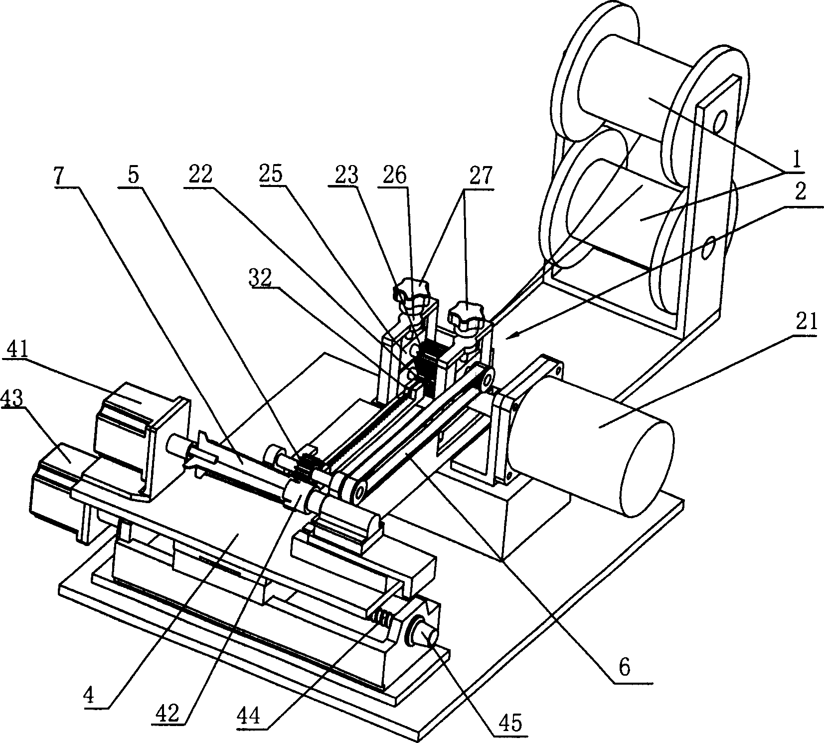
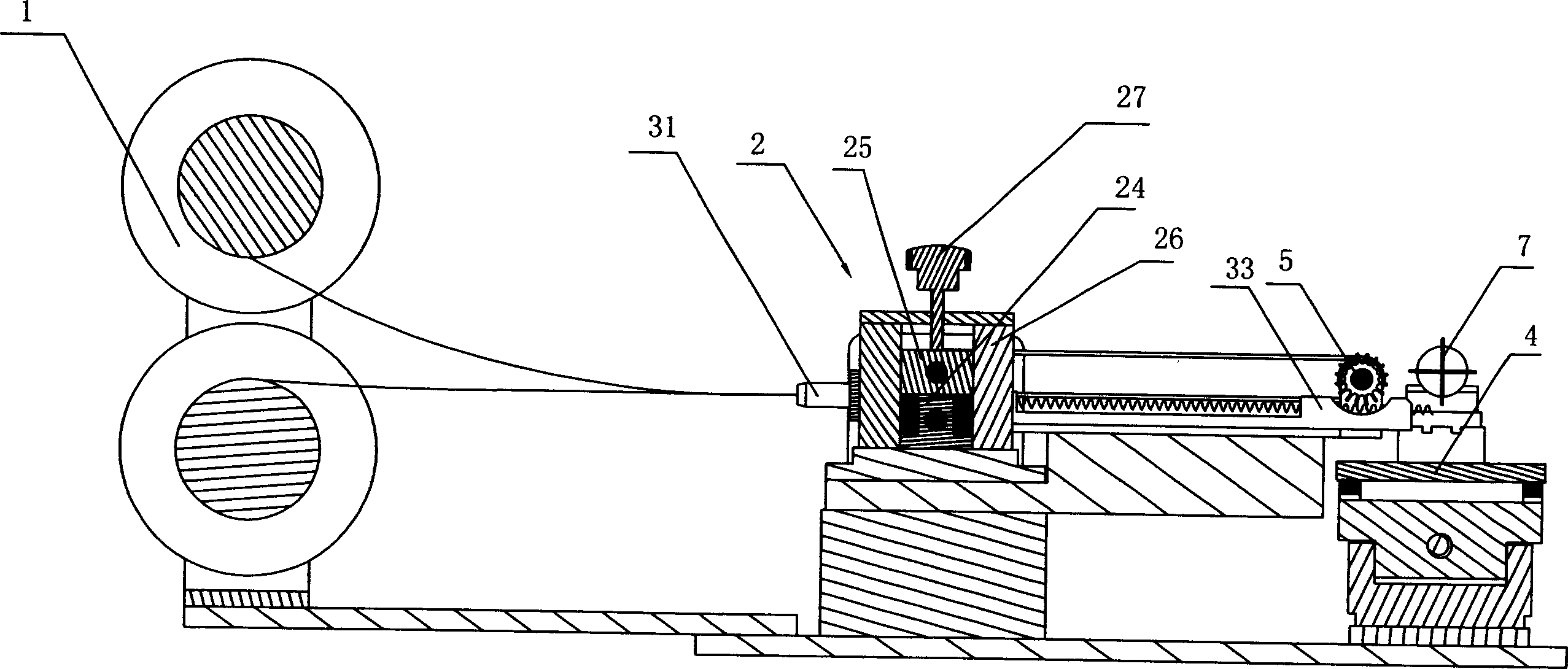
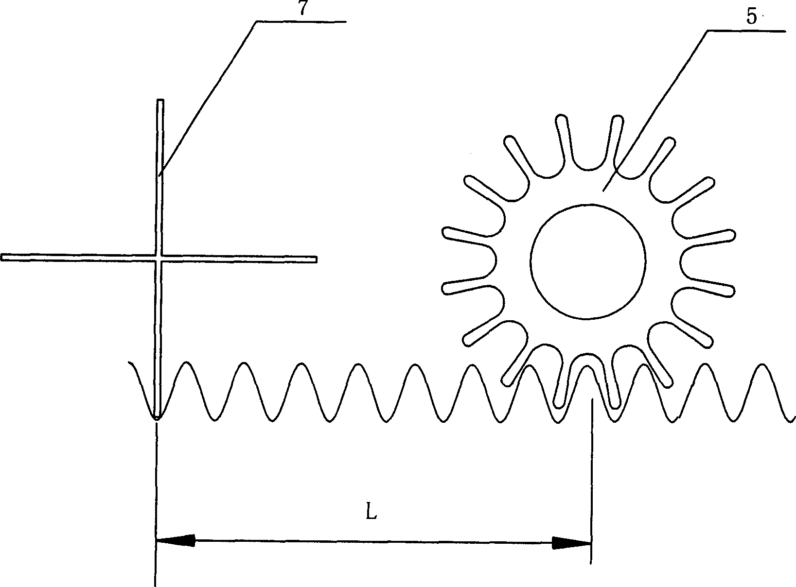
[0018] Embodiment 1: A numerically controlled corrugated wire winding machine, comprising a wire storage wheel 1, a corrugated wire former 2 and a workpiece table 4, a workpiece rotating motor 41 and a workpiece fixture 42 are arranged on the workpiece table 4, and the corrugated wire former 2 and A wire reel 5 is arranged between the workpiece tables 4, an incoming wire guide block 31 is arranged between the wave wire former 2 and the wire storage wheel 1, and an outlet guide block 32 is arranged at the outlet of the wave wire former 2, and the wire reel 5 A winding guide block 33 is arranged on the side, and two guide grooves are arranged on the three guide blocks 31, 32, 33. The wave wire former 2 includes a wave wire main rolling wheel 22 driven by a feed motor 21 and a wave wire The wave line corresponding to the main roll 22 is from the rolling wheel 23, and the wave line main rolling wheel 22 is arranged on the main rolling wheel axle seat 24 by the wheel shaft, and the ...
Embodiment 2
[0019] Embodiment 2: A numerically controlled corrugated wire winding machine, comprising a wire storage wheel 1, a corrugated wire former 2 and a workpiece table 4, a workpiece rotating motor 41 and a workpiece fixture 42 are arranged on the workpiece table 4, and the corrugated wire former 2 and A wire reel 5 is arranged between the workpiece tables 4, an incoming wire guide block 31 is arranged between the wave wire former 2 and the wire storage wheel 1, and an outlet guide block 32 is arranged at the outlet of the wave wire former 2, and the wire reel 5 A winding guide block 33 is arranged on the side, and two guide grooves are arranged on the three guide blocks 31, 32, 33. The wave wire former 2 includes a wave wire main rolling wheel 22 driven by a feed motor 21 and a wave wire The wave line corresponding to the main roll 22 is from the rolling wheel 23, and the wave line main rolling wheel 22 is arranged on the main rolling wheel axle seat 24 by the wheel shaft, and the ...
Embodiment 3
[0020]Embodiment 3: A numerically controlled corrugated wire winding machine, comprising a wire storage wheel 1, a corrugated wire former 2 and a workpiece table 4, a workpiece rotating motor 41 and a workpiece fixture 42 are arranged on the workpiece table 4, and the corrugated wire former 2 and A wire reel 5 is arranged between the workpiece tables 4, an incoming wire guide block 31 is arranged between the wave wire former 2 and the wire storage wheel 1, and an outlet guide block 32 is arranged at the outlet of the wave wire former 2, and the wire reel 5 A winding guide block 33 is arranged on the side, and two guide grooves are arranged on the three guide blocks 31, 32, 33. The wave wire former 2 includes a wave wire main rolling wheel 22 driven by a feed motor 21 and a wave wire The wave line corresponding to the main roll 22 is from the rolling wheel 23, and the wave line main rolling wheel 22 is arranged on the main rolling wheel axle seat 24 by the wheel shaft, and the w...
PUM
 Abstract
Description
Claims
Application Information
 - R&D
- Intellectual Property
- Life Sciences
- Materials
- Tech Scout
- Unparalleled Data Quality
- Higher Quality Content
- 60% Fewer Hallucinations
Browse by: Latest US Patents, China's latest patents, Technical Efficacy Thesaurus, Application Domain, Technology Topic, Popular Technical Reports.
© 2025 PatSnap. All rights reserved.Legal|Privacy policy|Modern Slavery Act Transparency Statement|Sitemap|About US| Contact US: help@patsnap.com