Tail rudder operated rotor flying robot

A flying robot and tail rudder technology, applied in the field of robotics, can solve the problems of inconsistent hysteresis effect, uncertain flight control, and difficulty in miniaturization, and achieve the effect of improving the design mode, reducing the difficulty of miniaturization, and having a simple structure.

CN1807184AInactive Publication Date: 2006-07-26SHANGHAI JIAO TONG UNIV
0 Cites 5 Cited by

Patent Information

Authority / Receiving Office
CN · China
Patent Type
Applications(China)
Current Assignee / Owner
Publication Date
2006-07-26
Estimated Expiration
Not applicable · inactive patent

Smart Images

  • Figure 1
    Figure 1
  • Figure 2
    Figure 2
  • Figure 3
    Figure 3
Patent Text Reader

Abstract

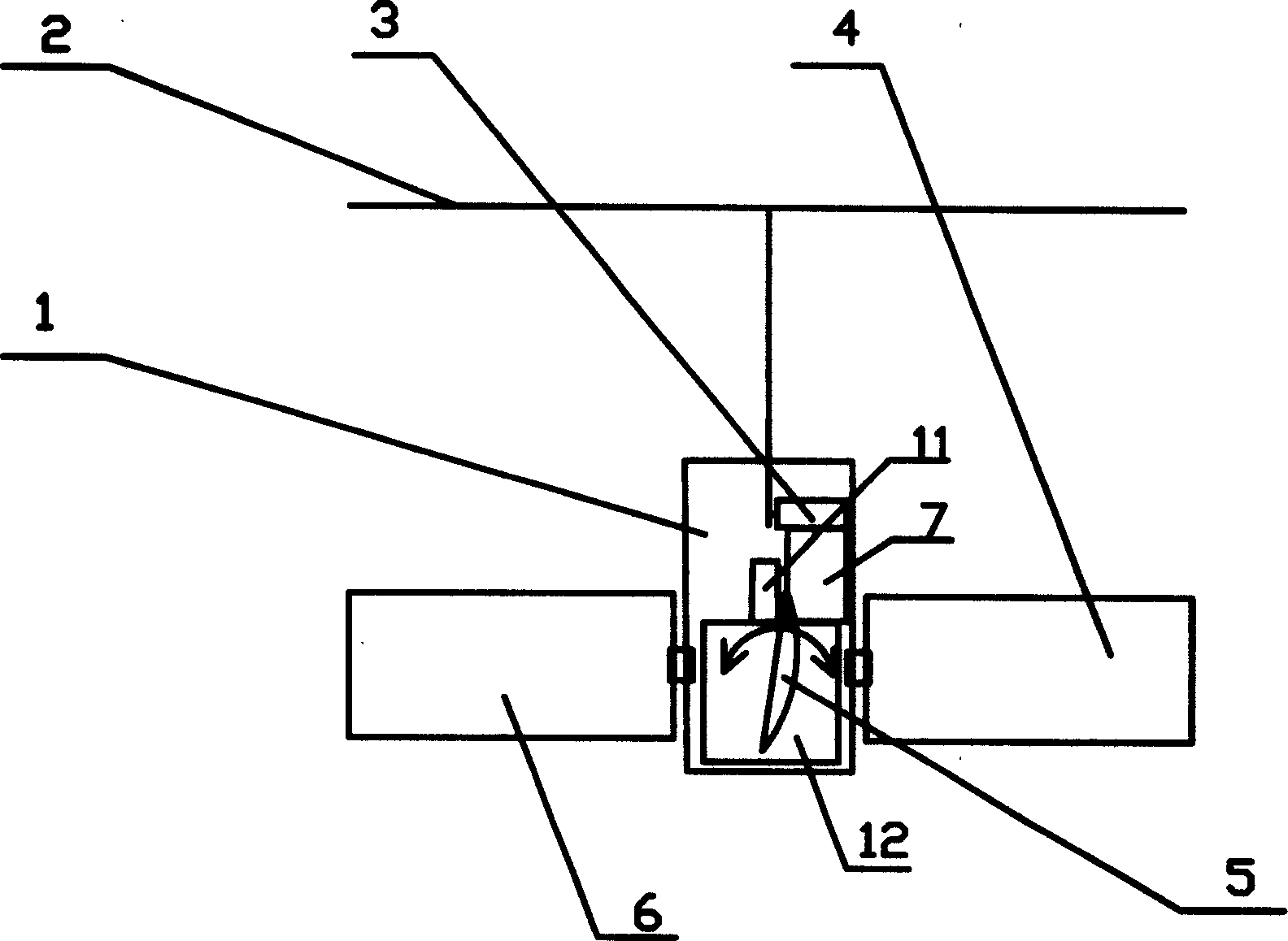
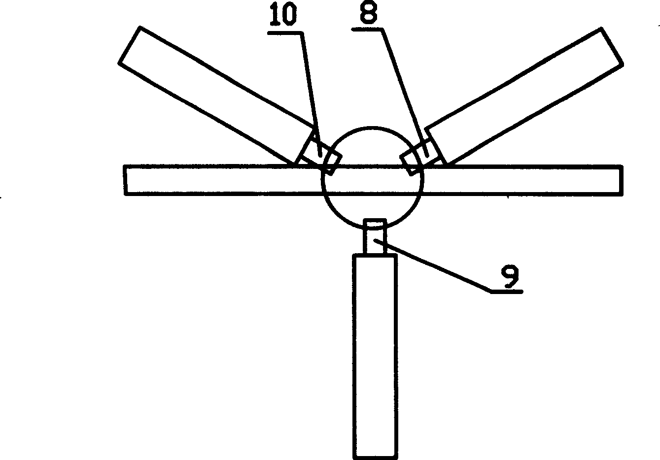
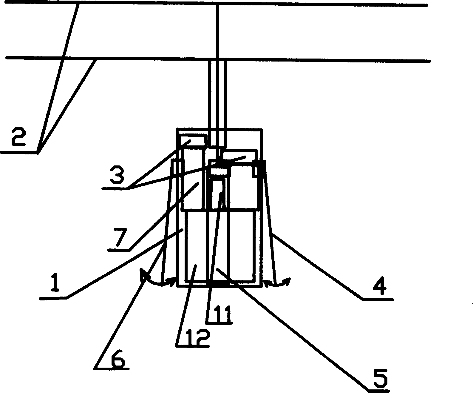
The invention relates the tail rudder rotor flight robot, comprising body, rotor, rotor driver, three tail rudders, tail rudder controller, three tail rudder drivers, attitude sensor and power source. The rotor driver is directly fixed on body, and the output of it is connected with rotor. The tail rudder controller and three tail rudder drivers is installed under body, the tail rudder controller auto produces the tail rudder driver order according to the information of attitude sensor and the order of operation crews, on the output end of three tail rudder drivers there are tail rudder, the attitude sensor is installed in the center of body, and the power source is installed on the two sides of body. The invention has the advantages of high automation, simple structure, and light additional weight. The tail rudder can utilize the downwash air flow coursed by rotary-vane turning, replacing the auto inclinator, and realizing the new pattern flight mode without tail paddle.
Need to check novelty before this filing date? Find Prior Art

Description

technical field

[0001] The invention relates to a device in the technical field of robots, in particular to a rudder-controlled rotor flying robot. Background technique

[0002] Most of the existing rotary-wing flying robots adopt the helicopter structure, which has a very adverse effect on the miniaturization of its own size. The rotor control mechanism of a manned helicopter is very complicated, especially its core component - the structure of the automatic tilter is even more complicated. For general unmanned helicopters, due to the limited load capacity and relatively simple structure, certain simplifications have been made on the rotor control mechanism. The load capacity of the micro-miniature flying robot is very small, and even needs to be measured in grams. It is still difficult to fully achieve the design goal only by further simplifying it and simply shrinking the rotor control mechanism. When designing the control mechanism of a micro-rotor flying robot, the co...

Examples

Embodiment Construction

[0012] like figure 1 , 2 As shown, the present invention includes: body 1, rotor 2, rotor controller 3, rudder 4, rudder 5, rudder 6, rudder controller 7, rudder driver 8, rudder driver 9, rudder driver 10. Attitude sensor 11 and power source 12. The connection relationship is: the rotor drive controller 3 is directly fixed on the body 1, controlled by the PWM mode of the DC motor, and its output terminal is fixedly connected with the rotor 2. The tail rudder controller 7, the tail rudder driver 8, the tail rudder driver 9, and the tail rudder driver 10 are arranged below the body 1, and the tail rudder controller 7 automatically generates the tail rudder drive command according to the information of the attitude sensor 11 and the order of the operator, The tail rudder 4 is set at the output end of the tail rudder driver 8, the tail rudder 5 is set at the output end of the tail rudder driver 9, the tail rudder 6 is set at the output end of the tail rudder driver 10, and the ...