Auspuffsystem für ein fahrzeug

A technology for exhaust devices and vehicles, which is applied to exhaust devices, mufflers, engine components, etc., can solve problems such as slow catalyst activation, and achieve the effect of suppressing enlargement and improving the ease of piping connection.

Inactive Publication Date: 2006-08-02
HONDA MOTOR CO LTD
View PDF1 Cites 6 Cited by
  • Summary
  • Abstract
  • Description
  • Claims
  • Application Information

AI Technical Summary

Problems solved by technology

[0006] In addition, as in the past, a catalyst is installed inside the muffler, and the activation of the catalyst is slow in the cold state at the moment when driving starts.

Method used


Image

  • Auspuffsystem für ein fahrzeug
  • Auspuffsystem für ein fahrzeug
  • Auspuffsystem für ein fahrzeug

Examples


Embodiment Construction

[0040] Hereinafter, one embodiment of the present invention will be described with reference to the attached drawings.

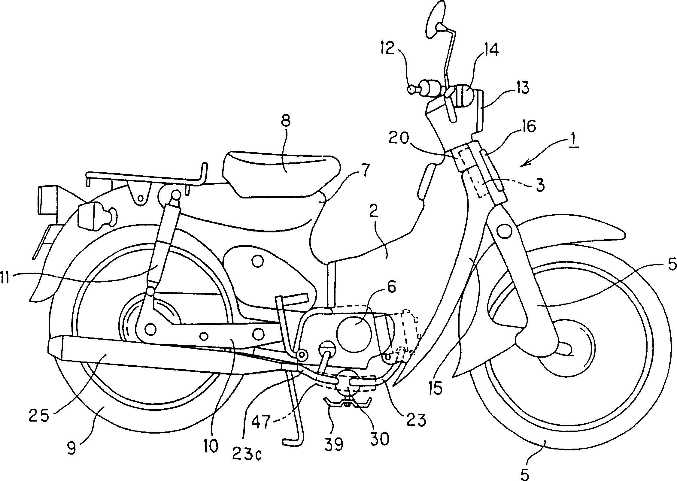
[0041] exist figure 1 Among them, 1 is a motorcycle (vehicle), and this motorcycle 1 is constituted by covering the front part of a pressure frame (pressframe) 7 with a cover 2 . On the head pipe 3 at the front part of the pressure frame, a front fork 5 for supporting the front wheel 4 is supported.

[0042] In addition, the engine 6 is mounted on the lower part of the casing 2, and the fuel tank (not shown) is provided inside the rear of the casing 2. The above-mentioned pressure frame 7 is formed to connect the appearance, and a seat is extended on the top thereof. Chair 8. A rear fork 10 supporting a rear wheel 9 is swingably supported under the pressure frame 7 , and a rear shock absorber unit 11 is provided between the rear fork 10 and the rear portion of the vehicle frame. A handlebar 12 is provided on the top of the steering rod from which the head...


PUM


Abstract

The invention discloses a vehicle discharging device, which connects a silencer (25) in a discharging device of a vehicle of a discharge pipe (23) which is extended from a motor (6), a catalytic convertor (30) is prepared in the middle way of the discharge pipe (23) and / or the silencer (25), in the catalytic convertor (30), a leading-in pipe (55) and a discharge pipe (57) which lead to a catalytic room (53) to discharge gas is centralized to allocate on one end side of the catalytic room. Thereby forming in the pattern of seeking distribution diversification of the catalytic convertor, and the invention can accelerate catalytic in a cold machine status to be activation.

Description

technical field [0001] The present invention relates to vehicle emission devices equipped with catalytic converters. Background technique [0002] Generally, there is known an exhaust system for a motorcycle in which a muffler is connected to an exhaust pipe extending from an engine (for example, refer to Patent Document 1). As such a vehicle exhaust device, a type in which the rear portion of the exhaust pipe is introduced into the inside of the muffler and the diameter of the rear portion of the exhaust pipe is enlarged rearwardly has been proposed in order to improve engine performance. In the above-mentioned conventional discharge device, generally, the catalytic converter is equipped with a catalyst chamber, and the introduction pipe of the exhaust gas leading to the catalyst chamber is connected to one side of the catalyst chamber, and the discharge pipe is connected to the other end of the catalyst chamber. side. [0003] (Patent Document 1) JP-A-6-10659 [0004] H...

Claims


Application Information

Patent Timeline
Patent Type & Authority Applications(China)
IPC IPC(8): F01N3/24
CPCY02A50/20
Inventor 高田康弘岛田信弘大久保克纪宫田博明楢崎康生
Owner HONDA MOTOR CO LTD
Why Eureka
Try Eureka