
Multistage turbocompressor

A technology of turbo compressors and compressors, which is applied to mechanical equipment, gear transmissions, machines/engines, etc., to achieve the effects of low cost, reduced volume, and expanded space

Active Publication Date: 2006-08-02
MAN ENERGY SOLUTIONS SA
View PDF3 Cites 15 Cited by
  • Summary
  • Abstract
  • Description
  • Claims
  • Application Information

AI Technical Summary

Problems solved by technology

This requires additional construction space

Method used


Image

  • Multistage turbocompressor
  • Multistage turbocompressor
  • Multistage turbocompressor

Examples


Embodiment Construction

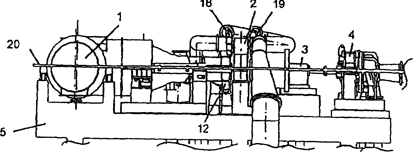
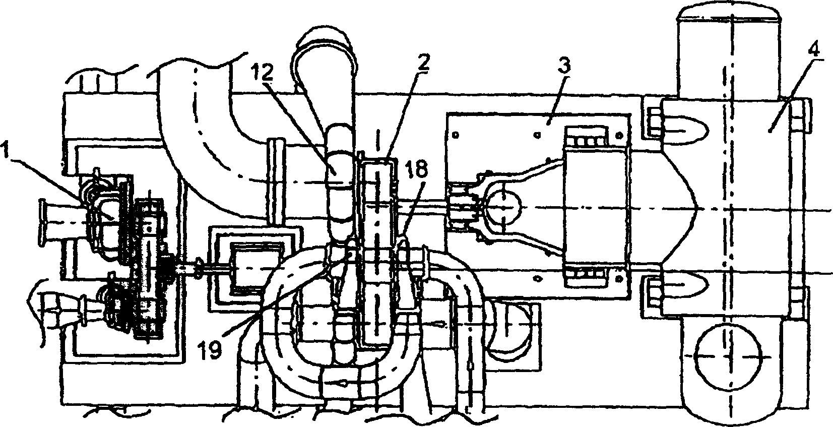
[0010] figure 1 The machine drive line shown is part of a chemical plant for the treatment and further processing of gases. This machine transmission line is made up of power unit 1 and transmission compressor 2. According to the type of chemical equipment, the machine transmission line may also include a motor / generator 3 and an expander 4 . Each unit is connected with each other and installed on a base that is on the concrete or steel foundation, that is, the machine platform 5 . Below the machine platform 5 are a plurality of coolers, a condenser and other units required for the operation of the equipment.

[0011] The power unit 1 is preferably formed as a steam turbine, the output shaft of which is connected to the drive shaft 6 of the downstream drive compressor 2 . The gear compressor 2 is a multi-stage turbo compressor with an integrated gear and is used for compressing gas.

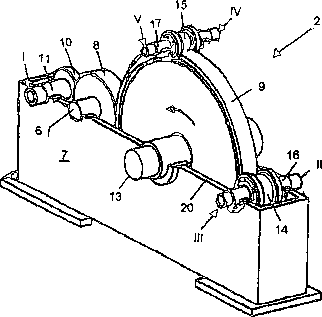
[0012] according to image 3 The drive compressor 2 comprises a housing 7 in which a dri...


PUM


Abstract

The turbocompressor has a geared compressor (2) with an integrated gear including a central greater wheel (9). The gear has a set of pinions that meshes with the greater wheel, where each pinion is mounted in a manner to rotate in unison with a respective pinion shaft. A set of bladed wheels respectively of one of a set of compressor stages, and a base frame on which individual units are assembled by a common central plane.

Description

technical field [0001] The invention relates to a multistage turbocompressor with the features stated in the preamble of claim 1 , which is designed as a driven compressor with an integrated transmission. Background technique [0002] Known drive compressors (DE 974 418, EP 0 440 902 B1, EP 1 302 668 A1) are characterized by a bull gear meshing with a plurality of pinions. One or two compressor stages are fastened to the pinions in each case. The pinion surrounds the bull gear, which is directly driven through the shaft of the bull gear to the drive shaft. Another possibility for connecting the power unit to the drive compressor is via a drive pinion, which likewise meshes with the bull gear, like the pinion of the compressor stage. Due to the structure of the drive compressor, the driving pinion is arranged under the bull gear. This drive compressor requires a vertical offset in the installation because the shaft of the bull gear and the shaft of the power unit are separ...

Claims


Application Information

Patent Timeline
Patent Type & Authority Applications(China)
IPC IPC(8): F04D25/16F16H1/02
CPCY02E20/18F04D25/163
Inventor M·罗德豪W-D·安德烈斯K·蒂梅
Owner MAN ENERGY SOLUTIONS SA
Learn More