Suspension arm

A suspension arm and suspension system technology, applied in the field of suspension arms, can solve the problems of inability to obtain dimensional accuracy, increase in operation steps and manufacturing costs, and achieve the effects of weight reduction, elimination of wall thickness parts, and uniform thickness

Inactive Publication Date: 2006-08-02
AISIN KEIKINZOKU CO LTD +1
View PDF4 Cites 16 Cited by
  • Summary
  • Abstract
  • Description
  • Claims
  • Application Information

AI Technical Summary

Problems solved by technology

However, since sufficient dimensional accuracy cannot be obtained for the distance between the shafts of the bearing parts at both ends, which requires particularly high dimensional accuracy, there is a problem that a large number of cutting processes must be performed after casting to ensure Dimensional accuracy or casting must be inspected for internal defects, resulting in increased work steps and manufacturing costs

Method used


Image

  • Suspension arm
  • Suspension arm
  • Suspension arm

Examples


Embodiment Construction

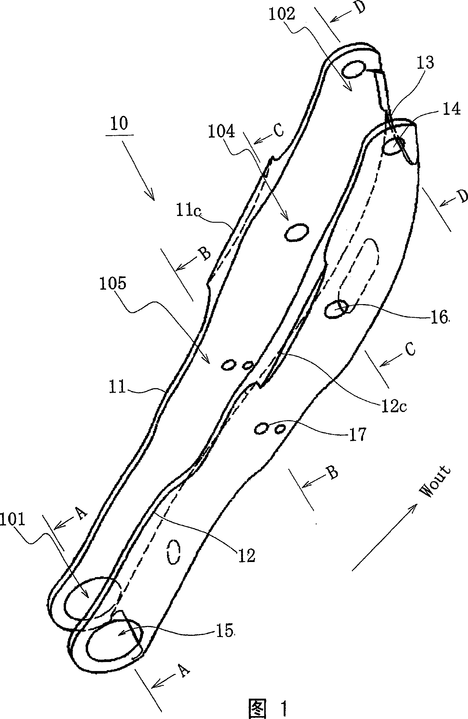
[0073] 1 is a perspective view of a suspension arm 10 of the present invention;

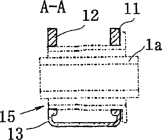
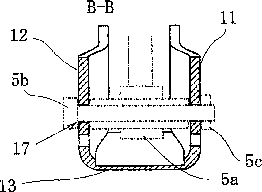
[0074] Fig. 2 is a cross-sectional view of various parts of the suspension arm, which is explained together with the assembly diagram of Fig. 4;

[0075] Fig. 2 (a) is the cross-sectional view (the cross-sectional view of the A-A line in Fig. 1) of the mounting part 101 of the suspension system component 1, and Fig. 2 (b) is the cross-sectional view of the mounting part 105 of the stabilizing link 5 (along the cross-sectional view of the 2 (c) is a sectional view of the mounting portion 104 of the shock absorber 4 (a sectional view along the line C-C in FIG. 1 ), and FIG. 2 (d) is a sectional view of the mounting portion 102 of the axle bracket 2. Section view (section view along the D-D line in Fig. 1), Fig. 2 (a)~(d) shows the peripheral parts (shock absorber 4 etc.) of suspension arm 10 by double-dot chain line, and it shows the state of its assembly, image 3 It is a cross-sectional view of ...


PUM


Abstract

The present invention provides a suspension arm made of an aluminum alloy extruded profile having a portion forming a bottom portion (43), portions forming at least two vertical walls (41, 42), and a horizontal rib (44) which connects the two vertical walls, wherein a suspension part lower end support portion is formed between the two vertical walls or at the bottom portion by removing a part of the horizontal rib. It is preferable to gradually change the interval between the two vertical walls in the portion in which the horizontal rib is removed.

Description

technical field [0001] The present invention relates to suspension arms for vehicles. Background technique [0002] When a vehicle makes a left turn, the Figure 24 As shown, a centrifugal force G acting rightward in the vehicle width direction is generated. This centrifugal force G is resisted by the reaction forces F1 and F2 generated by friction between the left tire 2L in the vehicle width direction and the right tire 2R in the vehicle width direction and the road surface, and a pressure P1 based on the centrifugal force G is generated on the suspension arm 100R on the right side. And the reaction force P2 that prevents it, on the left suspension arm 100L, the pulling force T1 based on the centrifugal force G and the reaction force T2 that prevent it are generated. In addition, when the vehicle is turning right, a force in the opposite direction to that in the above case acts. [0003] The suspension arm receives the above-mentioned force when the vehicle is cornering,...

Claims


Application Information

Patent Timeline
Patent Type & Authority Applications(China)
IPC IPC(8): B60G7/00
Inventor 布野和信安土一成刑部清人佐久间均
Owner AISIN KEIKINZOKU CO LTD
Why Eureka
Try Eureka