Method for regenerating a particle trap

A particle trap and mixer technology, applied in machine/engine, dispersed particle separation, chemical instruments and methods, etc., can solve problems such as inability to achieve temperature increase

Inactive Publication Date: 2006-08-02
EMITEC EMISSIONSTECHNIK
View PDF11 Cites 7 Cited by
  • Summary
  • Abstract
  • Description
  • Claims
  • Application Information

AI Technical Summary

Problems solved by technology

Due to the remote arrangement of the particle trap from the starter catalytic converter or the arrangement of additional components for exhaust gas purification between the starter catalytic converter and the particle trap, the required temperatures cannot be achieved in the particulate trap raised

Method used


Image

  • Method for regenerating a particle trap
  • Method for regenerating a particle trap
  • Method for regenerating a particle trap

Examples


Embodiment Construction

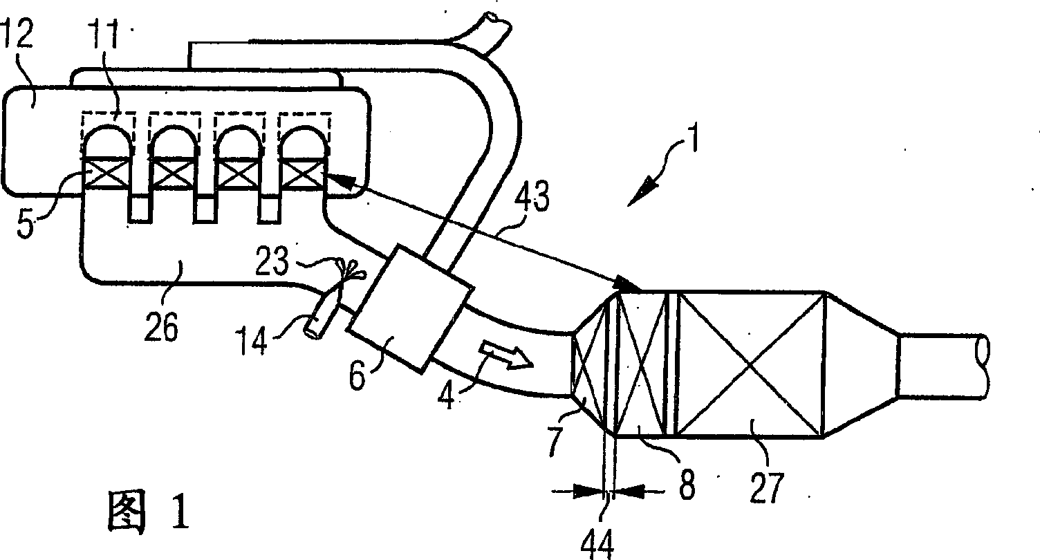
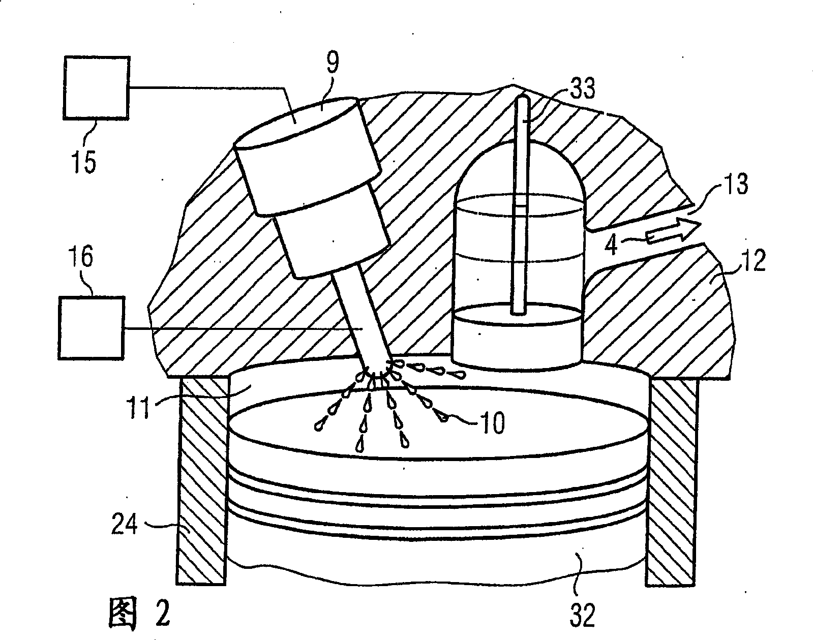
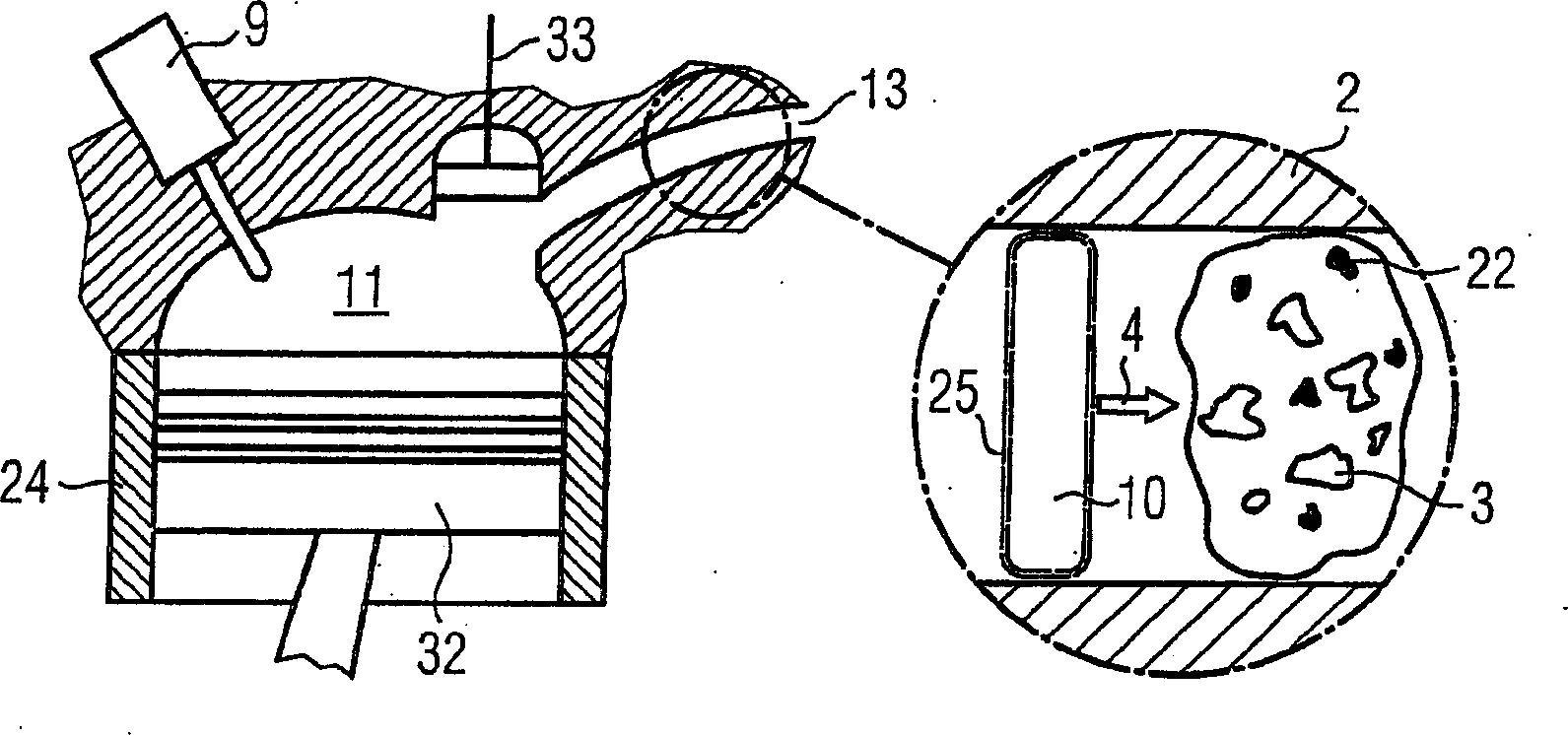
[0045] FIG. 1 schematically shows a perspective view of an exhaust system 1 for cleaning a gas flow 2 of pollutants 3 . In flow direction 4 of gas flow 2 , exhaust system 1 comprises at least a first catalytic converter 5 , a mixer 6 , a second catalytic converter 7 and a particle trap 8 . Furthermore, means are provided for supplying the reducing agent, which are arranged only upstream of the mixer 6 . Here in an internal combustion engine 12 , preferably a diesel engine for a passenger vehicle, fuel 10 is injected into the combustion chamber 11 of the individual cylinders 24 . The fuel 10 is combusted with highly compressed intake air and is then exhausted through exhaust duct 26 into the surrounding environment.

[0046] In the immediate vicinity of the internal combustion engine 12 , in particular at a distance of less than 70 cm, a plurality of first catalytic converters 5 are arranged, one of each first catalytic converter 5 being integrated in a tube of the exhaust gas...


PUM


Abstract

An exhaust system purifies a gas flow of harmful substances. The exhaust system contains at least device for supplying a reducing agent, a first catalytic converter, and a particle trap, in the direction of flow of the gas flow through the exhaust system. At least one other exhaust purification component is provided and / or there is a distance of at least 0.5 meters between the first catalytic converter and the particle trap. In addition, a mixer and a second catalytic converter are positioned directly upstream of the particle trap. A regeneration of the particle trap disposed in the exhaust system is carried out. A reducing agent is introduced into the exhaust gas system, only upstream of the turbocharger, for carrying out the regeneration process of the particle trap.

Description

technical field [0001] The invention relates to an exhaust gas treatment system for purifying a gas flow of harmful substances, which has a particle trap which can be regenerated discontinuously using a reducing agent. Furthermore, it also relates to a method for regenerating a particle trap. Background technique [0002] Exhaust systems have been continuously developed in the past due to legal regulations that place ever higher demands on exhaust systems in vehicle construction. In the process, many components are used which fulfill different functions in the exhaust system. For this purpose, for example, starter catalytic converters and pre-turbo catalytic converters are known, which have a particularly small volume so that after a cold start of the internal combustion engine the required starting temperature for the catalytic converter can be reached quickly. Furthermore, electrically heatable catalytic converters are known which likewise make it possible to improve the...

Claims


Application Information

Patent Timeline
Patent Type & Authority Applications(China)
IPC IPC(8): F01N3/023F01N3/035B01D53/94F01N3/025B01D53/96F01N3/022F01N3/20F01N3/28F01N13/02F01N13/04F02B3/06F02B37/00F02D41/02F02D41/40
CPCF01N2610/03F01N2330/38F01N2013/023B01D53/9495F02D41/405Y02T10/123B01D53/9454F01N13/02F02D41/029F01N2013/026F01N3/0253Y02T10/144F01N2240/00Y02T10/22F01N3/2821F02B3/06F01N3/0222F01N2340/02F01N3/035F02B37/00F01N13/04B01D53/96F02B2275/14F01N3/2828F01N13/0097F01N13/0093F01N13/009F01N13/011Y02A50/20Y02T10/12F01N3/023F01N3/02
Inventor W·莫斯R·布吕科
Owner EMITEC EMISSIONSTECHNIK
Why Eureka
Try Eureka