Inductance heating cooking appliance
A cooker and inductance technology, which is applied in the field of induction heating cookers, can solve the problems of lack of large firepower and insufficient circulation, and achieve the effects of reducing current peak value, reducing static loss, and reducing switching loss.
- Summary
- Abstract
- Description
- Claims
- Application Information
AI Technical Summary
Problems solved by technology
Method used
Image

Examples
Embodiment 1
[0038] Below, refer to Figure 1 to Figure 5 Embodiment 1 of the present invention will be described.
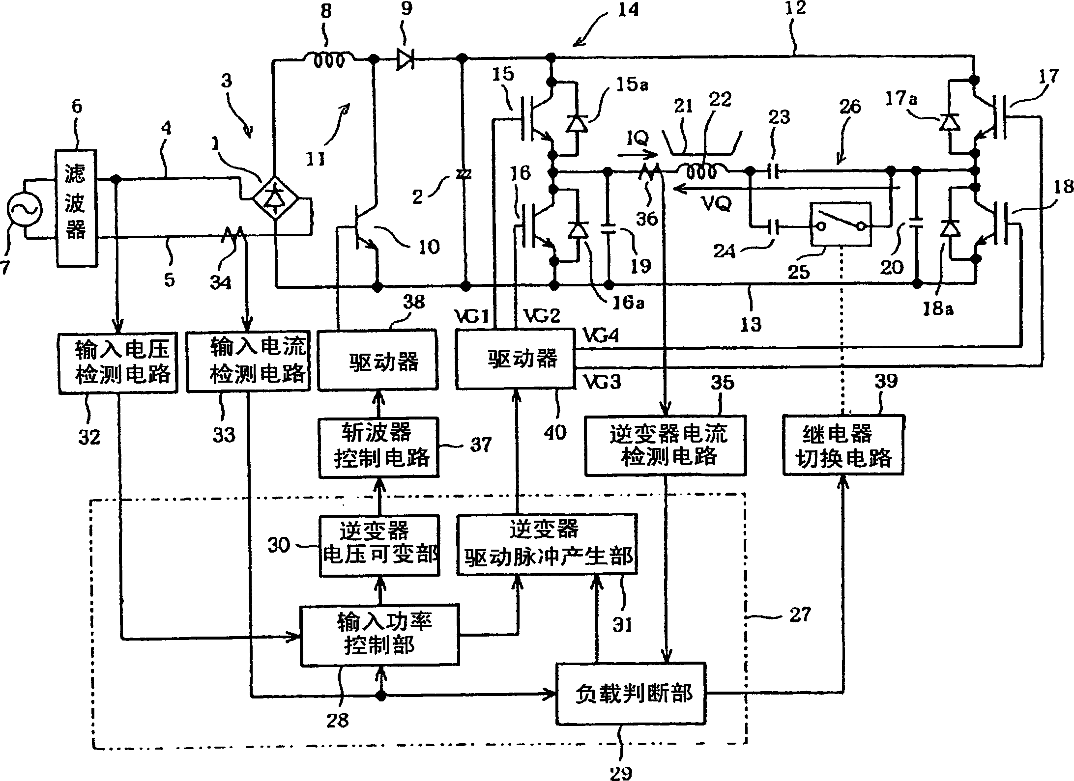
[0039] figure 1 is a block diagram showing the circuit of this embodiment. in the figure 1 Among them, the full-wave rectification circuit 1 together with the filter capacitor 2 constitutes a DC power supply circuit 3 . Its AC input terminal is connected to a 200V single-phase AC power supply 7 through AC power lines 4 and 5 and a noise filter 6 . The square output terminal of the full-wave rectification circuit 1 is connected to one terminal of the smoothing capacitor 2 through a reactor 8 and a high-speed diode 9 . The negative output terminal of the full-wave rectification circuit 1 is connected to the other terminal of the smoothing capacitor 2 . The NPN transistor 10 constitutes a chopper 11 as a DC voltage variable unit together with the reactor 8 and the high-speed diode 9 . Its collector is connected to the common junction of the reactor 8 and the high-speed ...
Embodiment 2
[0070] Figure 6 to Figure 8 It is Example 2 of the present invention. The same reference numerals are assigned to the same parts as those in the first embodiment described above, and the different parts will be described below.
[0071] Image 6 in, with figure 1 The difference is that the resonant capacitor 41 for heating the aluminum pan is connected instead of the first resonant capacitor 23 . The capacitance C41 of the resonant capacitor 41 is set to a value at which the resonant frequency becomes 87 kHz when the number of turns of the induction heating coil is 60 turns.
[0072] The aluminum pan is made of non-magnetic metal, so when a large inverter current flows, the pan may float or move sideways. The buoyancy force with which the pot is known to float is inversely proportional to the square root of the frequency. By further making the inverter current a high frequency, the floating of the pan can be suppressed.
[0073] Therefore, when the load judging part 29...
Embodiment 3
[0083] Figure 9 with Figure 10 It is embodiment 3 of the present invention. The same reference numerals are assigned to the same parts as those in the first embodiment described above, and the different parts will be described below.
[0084] Figure 9 in, with figure 1 The difference is that a zero-cross point detection circuit 42 is further provided, and an inverter phase difference detection unit 43 is provided in the control circuit 27 . The zero-cross point detection circuit 42 detects the zero-cross point of the inverter current detected by the inverter current detection circuit 35 . This zero-cross point detection signal VI0 is supplied to the inverter phase difference detection unit 43 . The phase difference detection unit 43 compares the zero-cross point detection signal VI0 with the gate signal VG1 from the inverter drive pulse generation unit 31 , detects the phase difference, and outputs a phase difference detection pulse DIF. This phase difference detecti...
PUM
 Abstract
Description
Claims
Application Information
 - R&D Engineer
- R&D Manager
- IP Professional
- Industry Leading Data Capabilities
- Powerful AI technology
- Patent DNA Extraction
Browse by: Latest US Patents, China's latest patents, Technical Efficacy Thesaurus, Application Domain, Technology Topic.
© 2024 PatSnap. All rights reserved.Legal|Privacy policy|Modern Slavery Act Transparency Statement|Sitemap