Rf-resonator tuning

A resonator and radio frequency technology, applied in resonators, resonant circuit drive/adjustment devices, waveguide devices, etc., can solve problems such as fragility and increased screw manufacturing costs

Inactive Publication Date: 2006-08-16
ALCATEL LUCENT SAS
View PDF0 Cites 4 Cited by
  • Summary
  • Abstract
  • Description
  • Claims
  • Application Information

AI Technical Summary

Problems solved by technology

On the other hand, when trying to keep the screw diameter small compared to the wavelength of free space (e.g. 3.5 mm for 85 GHz) with reduced manufacturing tolerances, screw manufacturing costs increase significantly
State-of-the-art components are also increasingly fragile to operate

Method used


Image

  • Rf-resonator tuning
  • Rf-resonator tuning
  • Rf-resonator tuning

Examples


Embodiment Construction

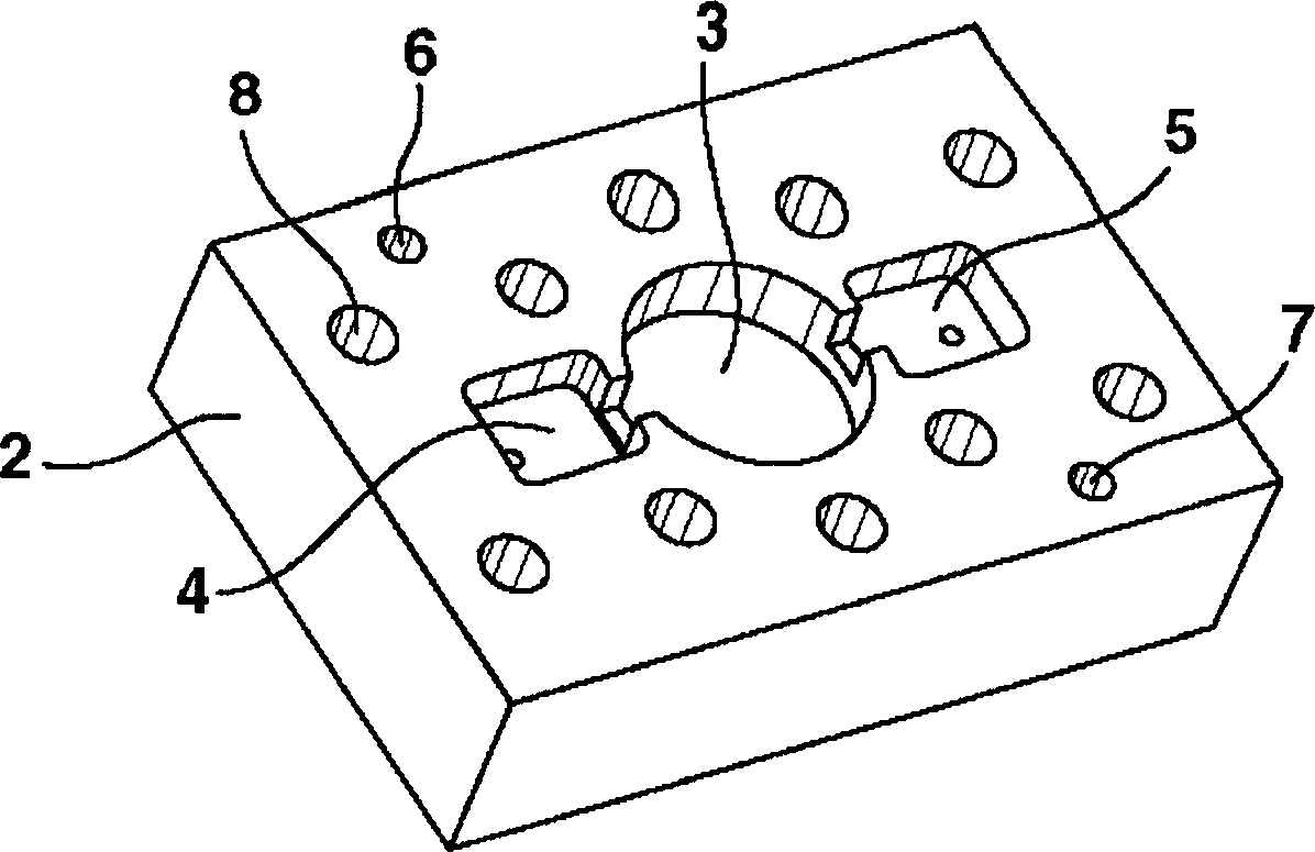
[0023] exist Figure 1a-1c The three steps for assembling the prototype RF resonator 1 are shown in . refer to Figure 1a , the milled rectangular block forms a resonator body 2 containing a centrally located cylindrical hole serving as a resonating cavity 3 . Two rectangular holes 4, 5 are formed in the resonator body 2 for receiving first and second connectors (not shown) inserted from the bottom of the resonator body 2 through two pin holes, the two rectangular holes 4 and 5 are located on the left and right sides of the resonant cavity 3 . In addition, two centering pin holes 6 , 7 and ten threaded holes 8 are formed on the resonator body 2 .

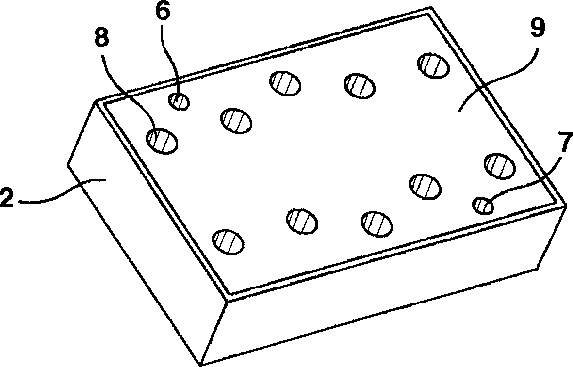
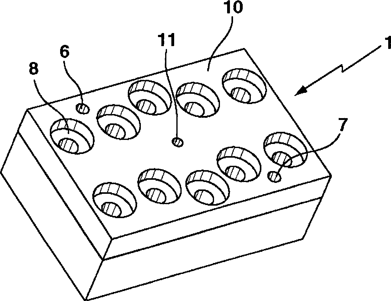
[0024] now refer to Figure 1b , Figure 1a The top surface of the resonator body 2 is covered by a thin metal foil 9 with holes at the positions of the pin holes 6, 7 and the threaded holes 8. Metal foil 9 covers the resonant cavity 3, and as Figure 1c It is secured by mounting a thick cover 10 on top of the resonator body 2 ...


PUM


Abstract

A RF-resonator (1) comprises a resonator body (2) with at least one resonant cavity (3). A conductive sheet material forms a surface area of the resonant cavity (3), the conductive sheet material being deformable by application of a mechanical force for tuning the resonator to a target frequency. A method for tuning the RF-resonator, comprising the following steps: measuring the resonance frequency of the resonant cavity (3), and deforming the conductive sheet material by applying an increasing mechanical force to the conductive sheet material until the target frequency of the resonant cavity (3) is reached.

Description

[0001] The present invention is based on the prior application EP 05 290 294.7 which is hereby incorporated by reference. technical field [0002] The invention relates to a radio frequency resonator comprising a resonator body with at least one resonator cavity and a method for tuning the radio frequency resonator. Background technique [0003] Electronic systems and user access systems using extremely high radio frequency (RF), such as optical data transmission equipment or millimeter-wave radio equipment, point-to-point or point-to-multipoint, and telematics equipment, require resonators with precisely tuned resonator frequencies and filters. [0004] In order to ensure that the original filter element to be fabricated can be tuned to the exact target frequency required, the prior art utilizes specific microwave tuning elements (eg metal screws / dielectric rods). These elements are generally commercially available, but expensive. The gold plating, the choice of special m...

Claims


Application Information

Patent Timeline
Patent Type & Authority Applications(China)
IPC IPC(8): H01P1/20H01P7/00H01P7/06H03J1/06
CPCH01P7/06H01P11/008
Inventor 伯恩哈德·容金格
Owner ALCATEL LUCENT SAS
Why Eureka
Try Eureka