Transmission pump and filter

A technology of filters, filter assemblies, applied in the direction of components, pumps, pump elements, etc. of pumping devices for elastic fluids, capable of solving problems such as noise, unpleasantness, pump damage, etc.

Inactive Publication Date: 2006-08-23
GENERAL MOTORS COMPANY
View PDF0 Cites 7 Cited by
  • Summary
  • Abstract
  • Description
  • Claims
  • Application Information

AI Technical Summary

Problems solved by technology

The pump's flow rate levels off and is not affected by further increases in pump speed; however, cavitation can cause pressure instability that interferes with the transmission control valve and potentially causes unpleasant noise
In more severe cases, air bubbles that burst at sonic speeds can cause damage to the pump itself

Method used


Image

  • Transmission pump and filter
  • Transmission pump and filter

Examples


Embodiment Construction

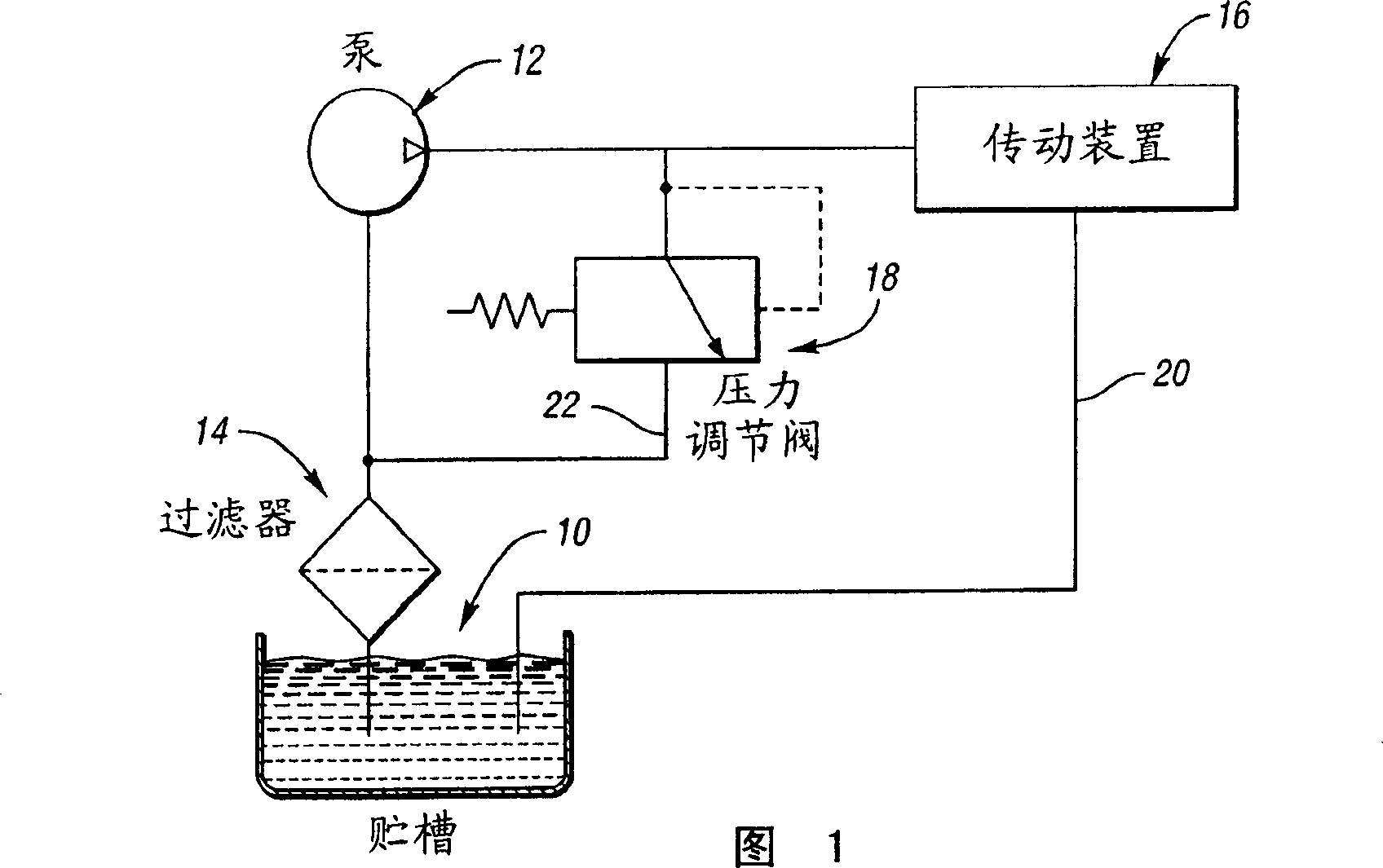
[0010] Referring to the drawings, in which like numerals indicate like or corresponding parts in the various figures, there can be seen in FIG. 1 a schematic representation of a tank or container 10 containing hydraulic fluid. The transmission controls the pump 12 to draw fluid from the container 10 through the filter assembly 14 . Pump 12 outputs pressurized hydraulic fluid to transmission system 16 . The maximum pressure at the pump output port is determined by the pressure regulator valve 18 which sends excess pump flow to the filter 14 . In accordance with a preferred embodiment of the present invention, the fluid first meets the transmission lubrication and pressure requirements, then the torque converter pressure requirements, then provides some lubrication and cooling, after which excess fluid is returned to the filter assembly 14 .

[0011] Lubrication flow and leakage fluid in the transmission system 16 returns to the container 10 through passages such as 20 . Exces...


PUM


Abstract

The filter housing has a filter outlet portion with a central filter outlet passage. The outlet portion includes a terminal end portion defining a filter nozzle. The filter nozzle forms a nozzle passage between the filter nozzle and the pump housing. The nozzle passage communicates with an annular recess formed in the filter outlet portion. The annular recess receives return bypassed hydraulic fluid from a regulator valve for distribution into an inlet stream of fluid flowing through the filter outlet passage. The inlet stream velocity is increased which increases the pressure at the pump inlet. The increased pressure at the pump inlet allows the pump to operate at higher speeds without cavitation.

Description

[0001] Cross References to Related Applications [0002] This application claims the benefit of US Provisional Application No. 60 / 589,275, filed July 20, 2004, which is hereby incorporated by reference in its entirety. Background technique [0003] A fixed displacement pump provides a theoretical fixed volume of oil during each cycle of the pump. The flow rate increases proportionally to the rotational speed of the pump. In practice, when the pump cavity cannot be completely filled with oil, the limit pump speed or high-speed filling limit (hereinafter collectively referred to as HSFL) is reached. A pump cavity that is not completely filled introduces air into the oil, creating a two-phase mixture that potentially causes cavitation. The pump's flow rate levels off and is not affected by further increases in pump speed; however, cavitation can cause pressure instabilities that interfere with the transmission control valves and potentially cause unpleasant noises. In more sev...

Claims


Application Information

Patent Timeline
Patent Type & Authority Applications(China)
IPC IPC(8): F04D29/66F04D29/70
Inventor J·C·舒尔茨K·约翰逊U·-J·宋
Owner GENERAL MOTORS COMPANY
Why Eureka
Try Eureka