Winding device and its winding method

A technology of winding and winding machine, which is applied in the direction of coil manufacturing, winding resistance components, etc., can solve the problems of difficulty in improving the yield of finished products, waste of wire use and waste.

Inactive Publication Date: 2006-08-23
廖木山
View PDF0 Cites 10 Cited by
  • Summary
  • Abstract
  • Description
  • Claims
  • Application Information

AI Technical Summary

Problems solved by technology

[0003] During the winding process of the existing wire winding device, the wire winding process is carried out by only rotating the flying fork wire winding machine without rotating the electronic component to be wound. The fork winding machine rotates together, otherwise it is very easy to cause the wire to be twisted, deformed, or even broken, which not only affects the processing, but also causes waste in the use of the wire, and the aforementioned winding method may also cause the wire to be difficult. Winding on the electronic components with a uniform force, and then resulting in the finished product, the stability of the product properties is not good when it is used, and the yield rate of the finished product is difficult to improve; moreover, if the component holder does not When holding the component to be wound, the flying fork winding machine will continue to idle until the user finds out and stops it, and the wires in between will become scrap materials, which will also cause waste of resources and costs

Method used


Image

  • Winding device and its winding method
  • Winding device and its winding method
  • Winding device and its winding method

Examples


Embodiment Construction

[0014] In order to further understand the structure, features and purpose of the present invention, the accompanying drawings and detailed description of preferred specific embodiments are as follows.

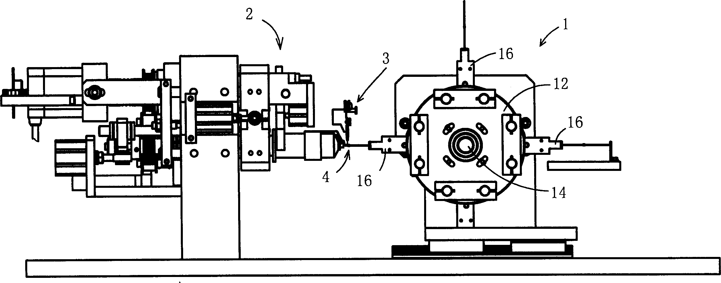
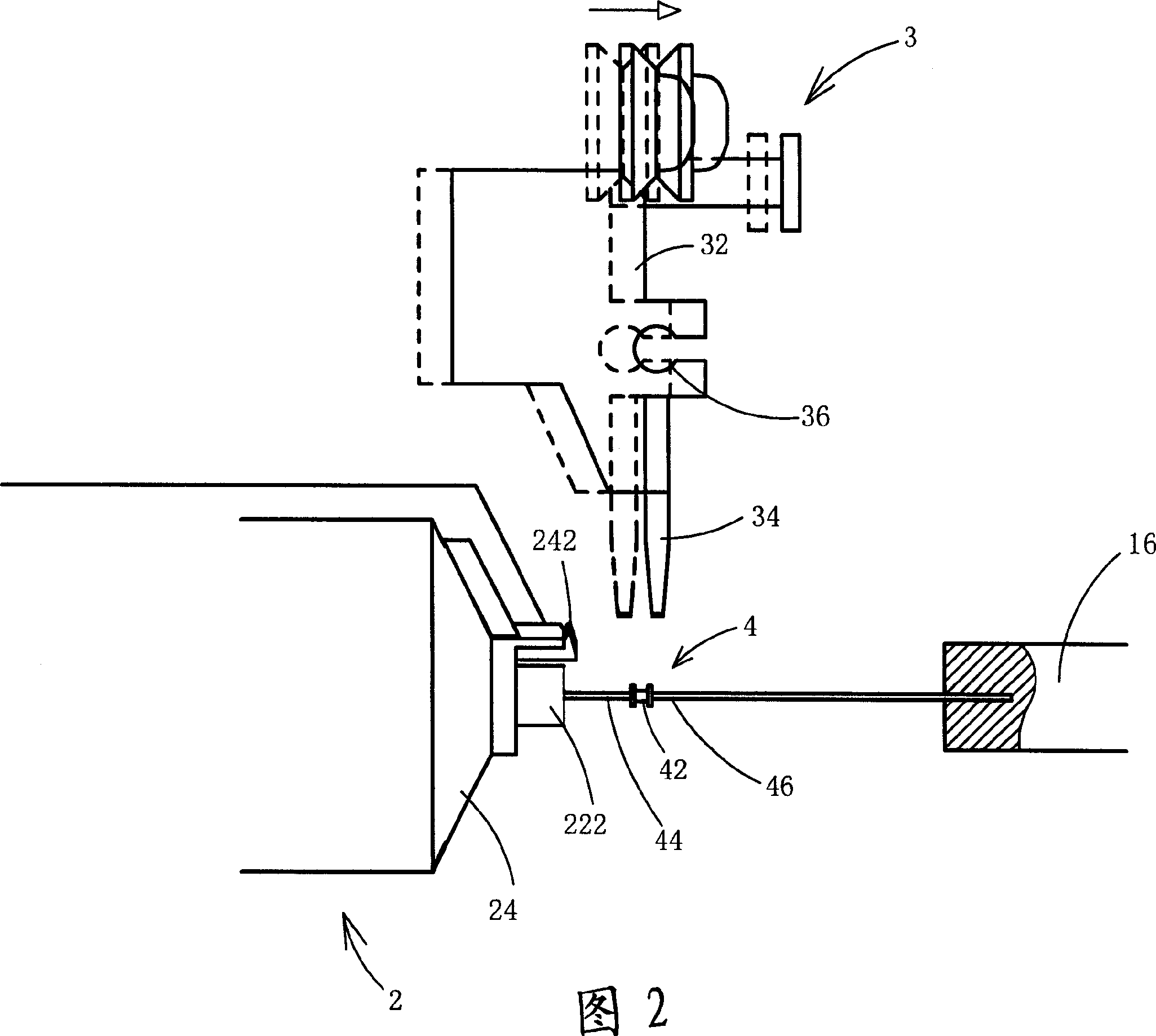
[0015] see figure 1 As shown in FIG. 2, it is a schematic diagram of a preferred embodiment of the winding device of the present invention. As shown in the figure, the thread winding device A includes a wheel device 1, a thread winding machine 2 and a wire supply device 3 respectively, the wheel device 1 has a wheel 12, and the wheel 12 is along the A rotating shaft 14 rotates, and a plurality of clamping assemblies 16 are respectively provided at the periphery of the rotating wheel 12, which can be used to clamp the pin 46 at one end of an electronic assembly 4 for processing; because in this embodiment, the The structure and operation method of the above-mentioned wheel device 1 belong to the application of the prior art, so it will not be repeated here.

[0016] Please als...


PUM


Abstract

Present invention relates to a wire winder. It contains an inner rotor shaft having collet for holding said electronic assembly connecting pin, an outer rotation sleeve set outer part of said inner rotor shaft, wire feeding device set between rotating wheel device and winder having a lead rod for winding wire on said electronic assembly.

Description

technical field [0001] The invention relates to a wire winding device and a wire winding method to achieve the purpose of evenly winding wires on electronic components. Background technique [0002] With the vigorous development of consumer electronics products, a large number of passive components are used in consumer electronics products, such as general resistance components, inductance components, etc., and among these types of electronic components, adopt Most of the electronic components are manufactured by wire winding process. The current electronic component mainly uses a winding device to carry out the winding process of the wire of the electronic component, and its main structure includes a rotating wheel and a flying fork winding machine. Wherein, the rotating wheel rotates along the center of its rotating shaft, and a plurality of component holders are arranged at appropriate positions on its periphery to hold electronic components to be wound. In addition, th...

Claims


Application Information

Patent Timeline
Patent Type & Authority Applications(China)
IPC IPC(8): H01F41/06H01C17/04
Inventor 廖木山
Owner 廖木山
Why Eureka
Try Eureka