Device for imparting ultrasonic vibration to resin material, method of melt-molding resin material using the device, and resin composition

A technology of resin composition and resin material, applied in the field of ultrasonic vibration application device, can solve the problems such as difficulty in showing the improvement effect of mechanical properties, limited effect, etc., and achieve excellent mechanical properties, easy resin modification, and improved impact resistance. Effect

Inactive Publication Date: 2006-08-23
IDEMITSU KOSAN CO LTD
View PDF4 Cites 19 Cited by
  • Summary
  • Abstract
  • Description
  • Claims
  • Application Information

AI Technical Summary

Problems solved by technology

However, in the technology described in this Patent Document 4, there is a problem that the effect of improving mechanical properties is difficult to be realized in injection molding, and the effect is limited.

Method used


Image

  • Device for imparting ultrasonic vibration to resin material, method of melt-molding resin material using the device, and resin composition
  • Device for imparting ultrasonic vibration to resin material, method of melt-molding resin material using the device, and resin composition
  • Device for imparting ultrasonic vibration to resin material, method of melt-molding resin material using the device, and resin composition

Examples


Embodiment approach

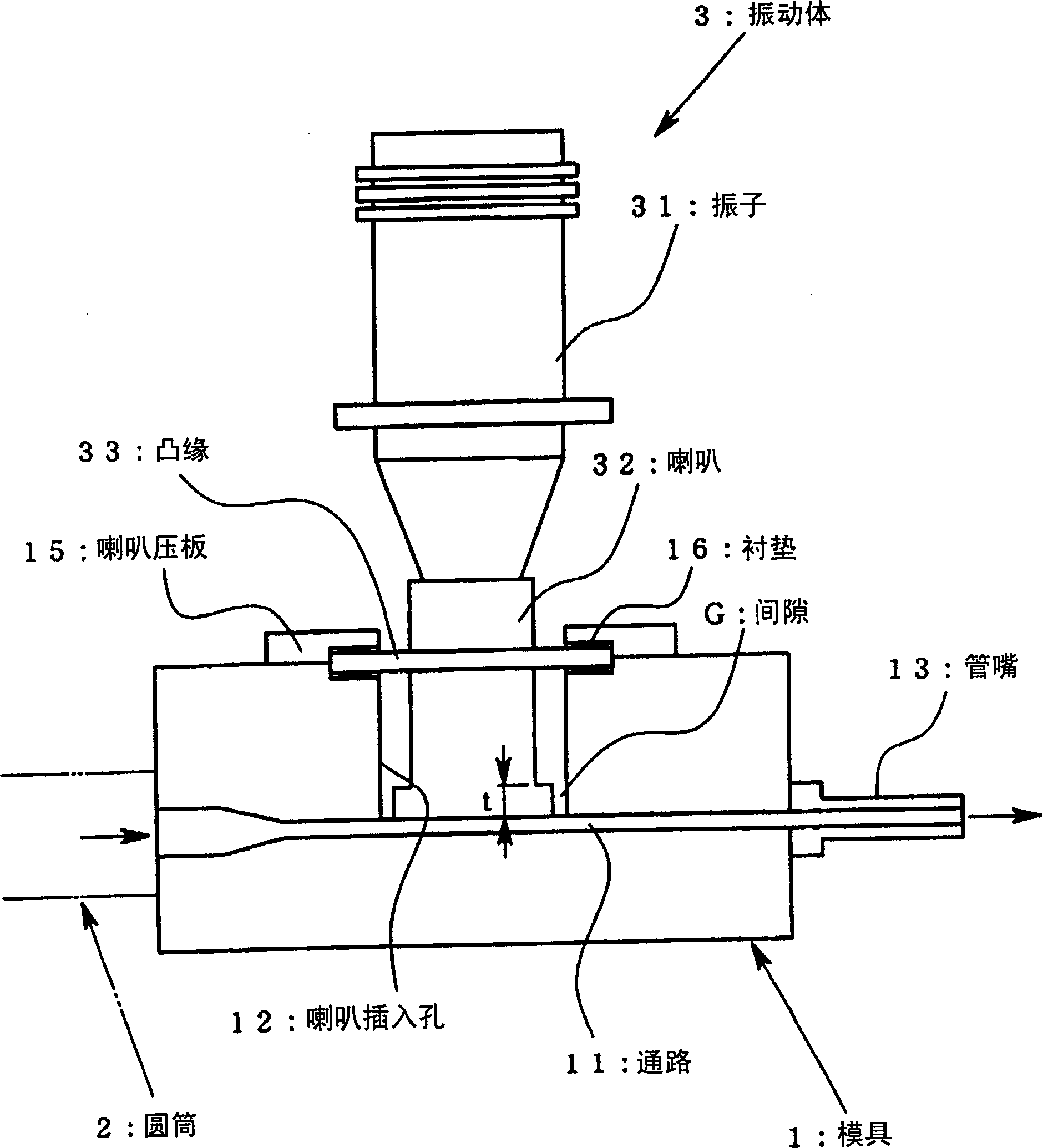
[0057] figure 1 It is a cross-sectional view of a die of an extruder equipped with a horn of an ultrasonic oscillator in the first embodiment of the present invention. In addition, in the "resin material" in the following description, unless otherwise specified, the resin material in a narrow sense naturally means a resin material containing a thermoplastic synthetic rubber (elastomer).

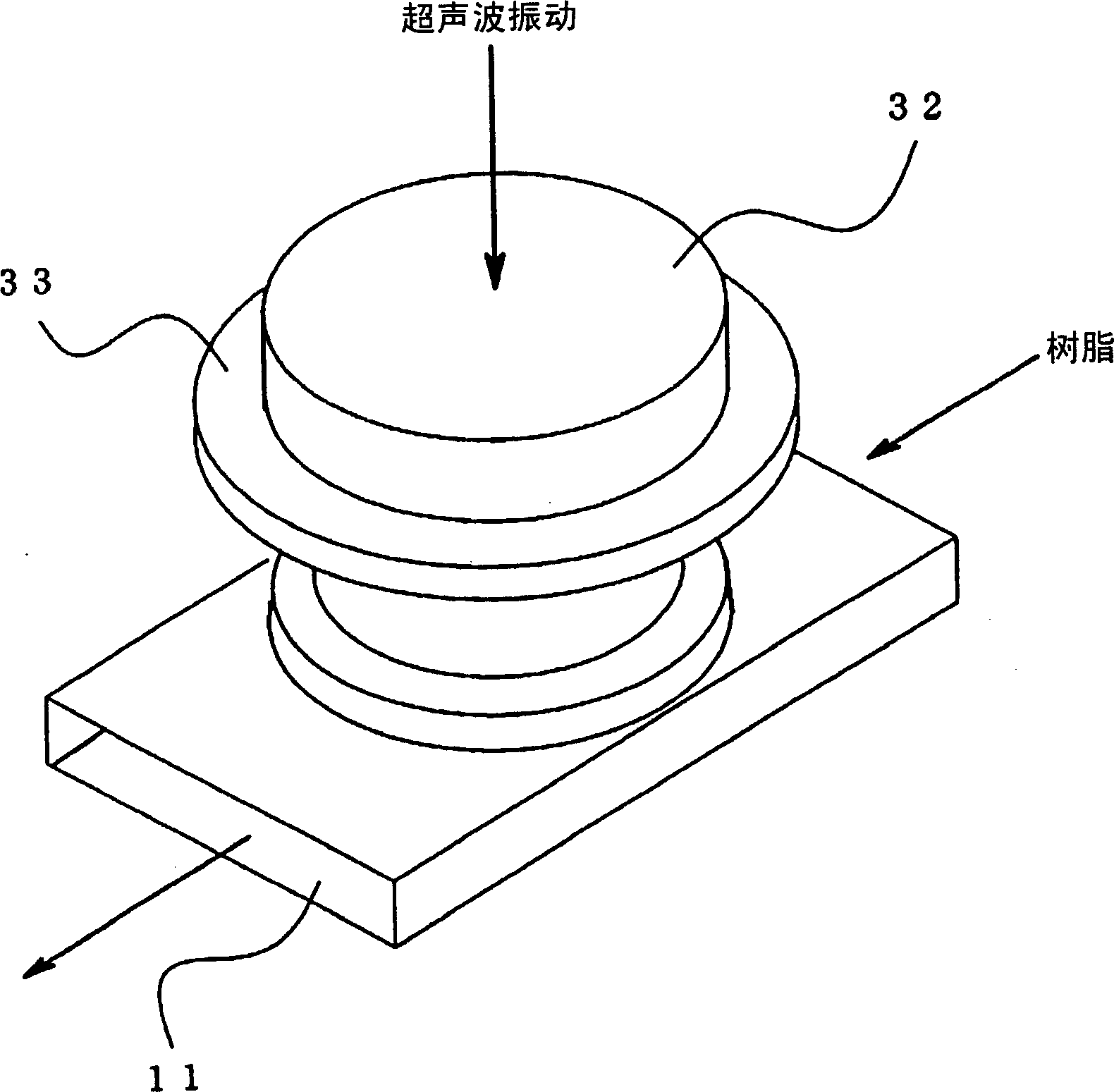
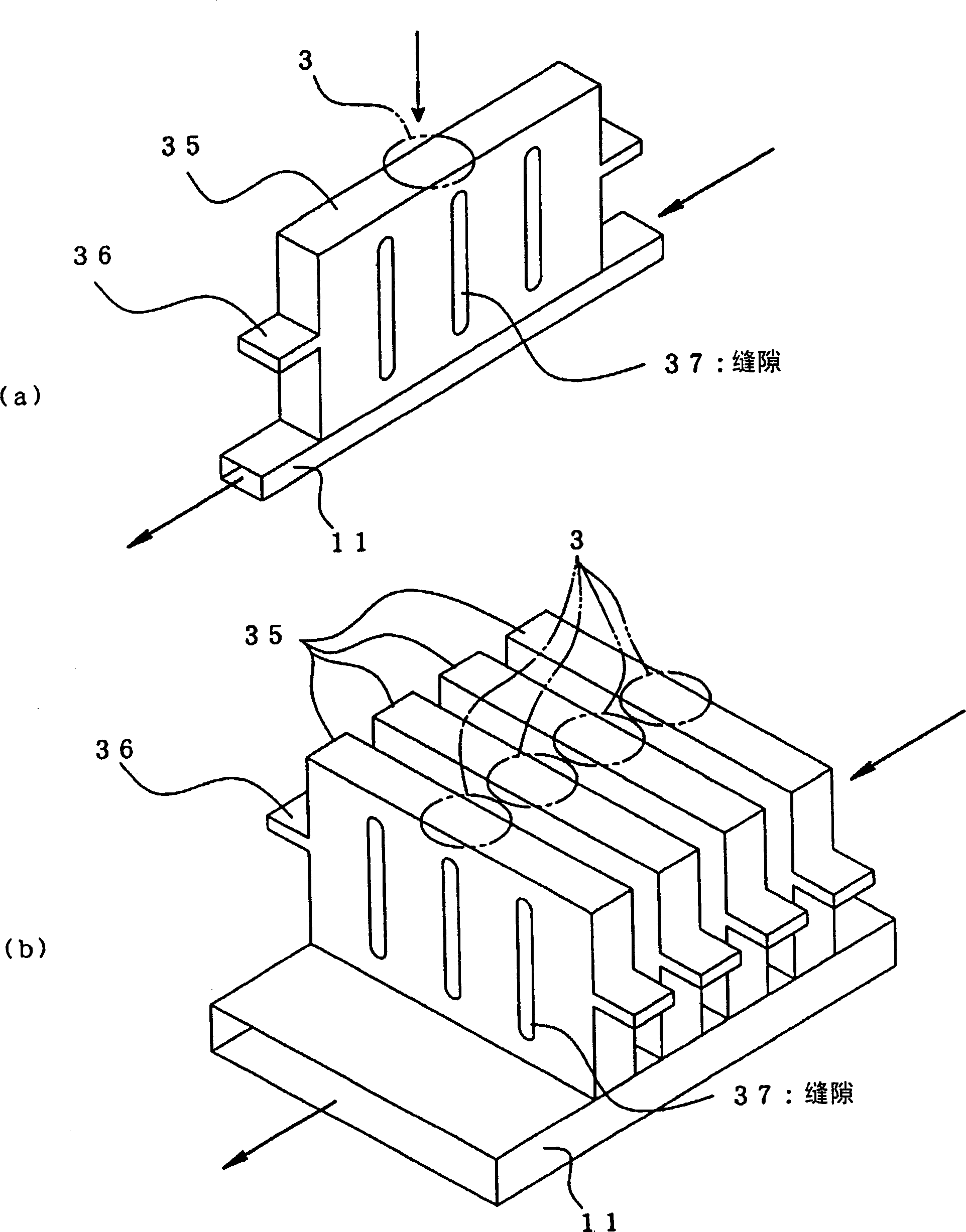
[0058] The resin material heated and melted by the cylinder 2 is supplied to the nozzle 13 through the passage 11 in the die 1 and extruded from the tip of the nozzle 13 . In the middle part of the mold 1, a vibrating body 3 is mounted. The vibrating body 3 is composed of a vibrator 31 connected to an ultrasonic supply source (not shown), and a horn 32 as a vibration transmission member attached to the tip of the vibrator 31 . In the middle part of the mold 1, a horn insertion hole 12 that reaches the passage 11 is formed. The horn 32 is inserted through the horn insertion hole 12 , and it...

no. 1 example

[0108] Resin material PP (polypropylene) / hard rubber

[0109] (1) Extruder: A TEX30H two-shaft extruder made by Nippon Steel Works was used, the cylinder temperature was 180°C, the die temperature was 180°C, the output was 2kg / h, and the number of screw revolutions was 100RPM.

[0110] Screw Size A: Standard Size

[0111] Screw size B: Strong stirring size

[0112] (2) Ultrasonic wave: A die with a horn for applying vibration was attached to the outlet of the biaxial extruder in the vertical direction with respect to the resin composition.

[0113] Frequency: 19.5kHz

[0114] Amplitude: 7μm

[0115] Speaker material: hard aluminum Eh=7×10^10Pa

[0116] (3) Material composition: In order to prevent the composition from being unbalanced, the master batch with the composition of PP / EPDM=JSR (mixing ratio 25:75) is diluted with PP, or diluted with PP and anhydrous maleic acid, and the following A The materials that are dry mixed by the combination of B and B are put into the ...

Embodiment 1

[0134] - Example 1: The vibration of the mold was suppressed by the spacer and the gap (the same applies to Examples 2 to 4). The impact strength is increased to a level that cannot be achieved in intensive stirring.


PUM

PropertyMeasurementUnit
particle diameteraaaaaaaaaa

Abstract

There is here disclosed a technique which can improve mechanical properties such as strength and impact resistance of molded articles without noticeably changing molding materials and rebuilding a molding apparatus. In a molding method in which the molding materials are fed to a mold disposed at one end of a cylinder while the molding materials in the cylinder are molten and kneaded, the molding materials can be molded while vibration is applied to the molding materials in a direction crossing a flow direction of the resin material at right angles. The vibration does not have to possess any node portion on a surface which contacts the molding material.

Description

technical field [0001] The present invention relates to an ultrasonic vibration applying device for applying ultrasonic waves to resin in a molten and flowing state, and in particular, to a resin material that can improve various physical properties and moldability of resin materials used in extrusion molding, injection molding, etc., so that high quality can be obtained. An ultrasonic vibration application device for a resin material of a molded article, a method for melt molding a resin material using the ultrasonic application device, and a resin composition. Background technique [0002] In a stirring device, extrusion molding device, and injection molding device for melting and stirring a resin material such as plastic to form a molded product of a desired shape, when the function of the formable resin material is improved, and various resins are mixed. The improvement of agitation or compatibility of resin materials, the improvement of dispersibility when formulating a...

Claims


Application Information

Patent Timeline
Patent Type & Authority Applications(China)
IPC IPC(8): B29B7/80B29C47/36B29C45/46B29B7/90B29C45/56B29C45/58B29C48/05B29C48/14B29C48/285
CPCB29B7/36B29C45/568B29C47/0071B29C45/585B29C47/385B29B7/90B29C47/0014B29C48/397B29C48/05B29C2948/92704B29C48/14B29C48/285B29C45/46B29B7/80
Inventor 末次义幸大槻安彦佐藤淳
Owner IDEMITSU KOSAN CO LTD
Why Eureka
Try Eureka