


Quick Research
Generate reliable direction feasibility study reports for your R&D in just a few steps.

Technical Q&A
Discover and master advanced knowledge NOW. Basics, ideas, possibilities, all at once.

Find Solutions
As an expert in R&D theories, this can generate solutions to your technical problems instantly.

Evaluate Feasibility
Analyze your overall solution with one click, know your potential R&D risks in advance.

Monitor Landscape
Get weekly tech updates, stay abreast of the latest tech innovations and key insights.
Coupling structure, resonator excitation structure and filter for coplanar-waveguide circuit
A coupling structure and resonator technology, applied in resonators, circuits, electrical components, etc., can solve the problems of resonant frequency variation of resonator 6, and achieve the effect of miniaturization and area saving
- Summary
- Abstract
- Description
- Claims
- Application Information
AI Technical Summary
Problems solved by technology
Method used
Image

Examples
Embodiment Construction
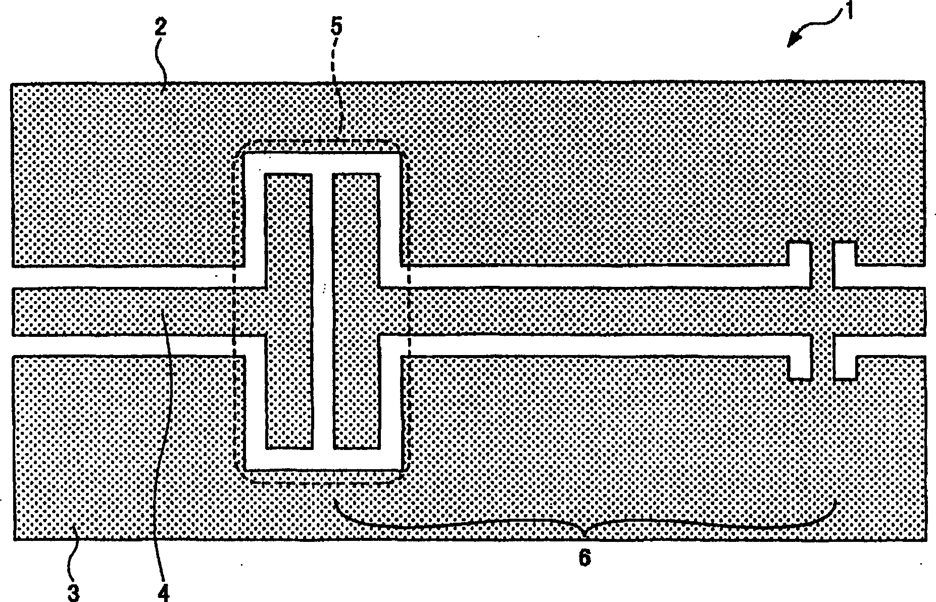
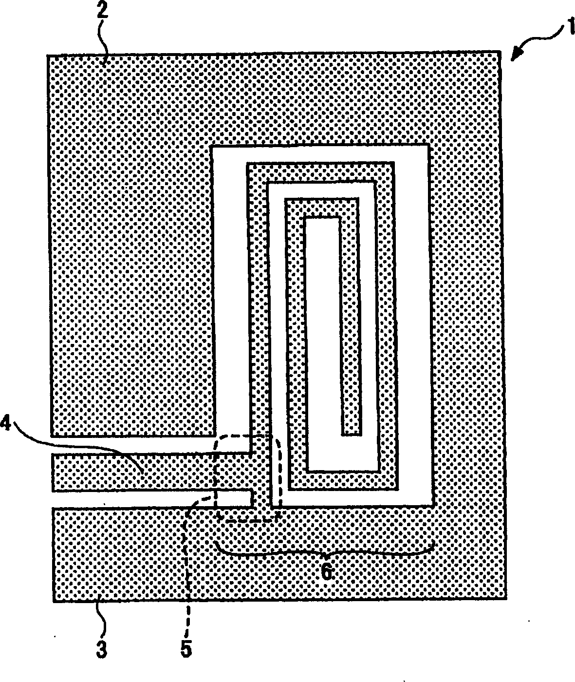
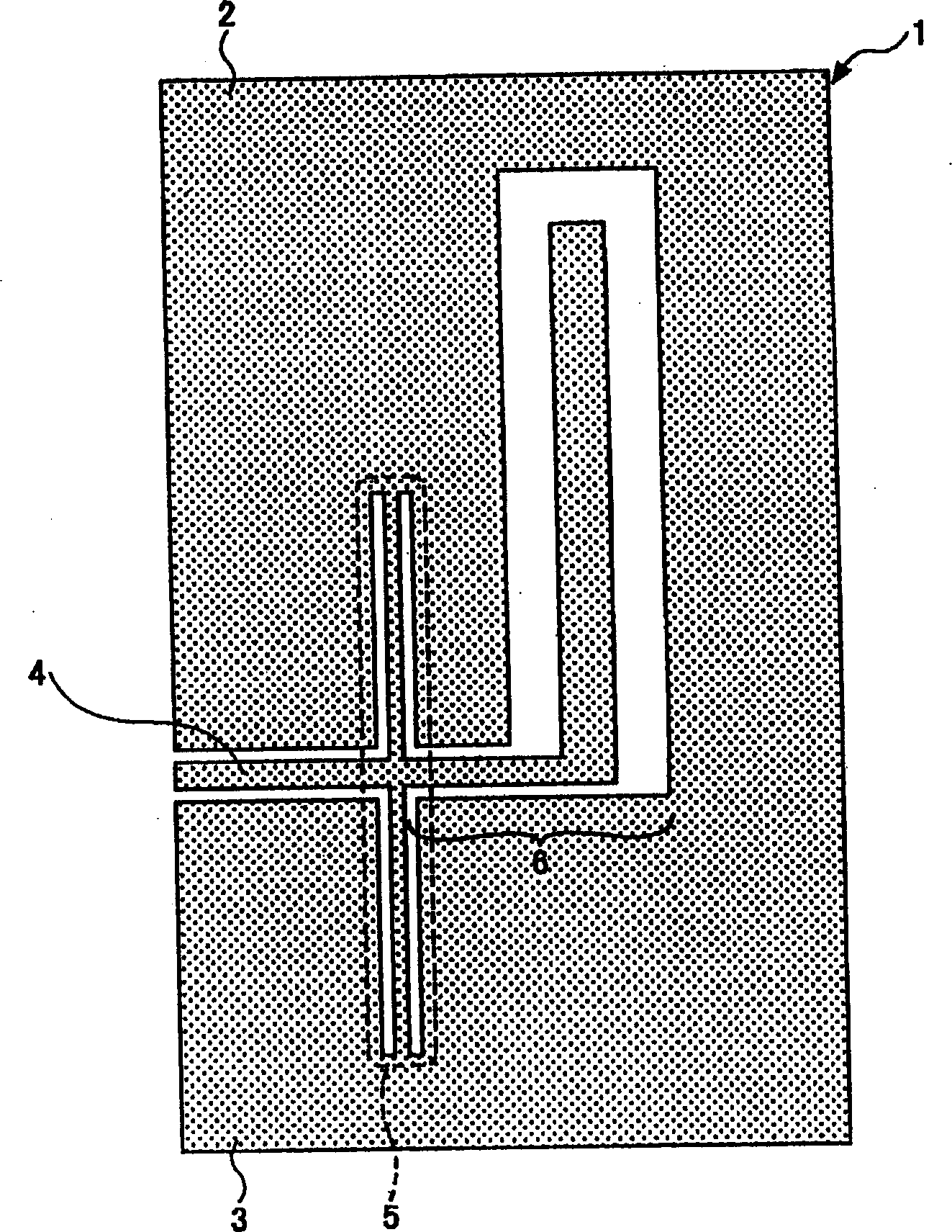
[0042] Hereinafter, preferred embodiments of the present invention will be described.
[0043] Figure 6 It is a plan view showing the excitation structure of the first embodiment of the present invention. exist Figure 6 In (a), ground conductors 2 and 3 are arranged on both sides of the coplanar planar circuit 1, and the excitation line 4 as a signal input and output line is arranged at the central part of the coplanar planar circuit 1, so that the cut-off waveguide of the accommodating circuit substrate Unnecessary propagation patterns are not generated within. In addition, the end of the excitation line 4 is bent into an L-shape and short-circuited to the ground conductor 2, and the short-circuit line is close to and opposed to the current concentration part of the resonator 6 via a gap part having a width of α. An excitation part 5 as an inductive coupling part is formed. The external coupling strength is determined by the width α of the gap, the length β of the short...
PUM
 Abstract
Description
Claims
Application Information
 - R&D Engineer
- R&D Manager
- IP Professional
- Industry Leading Data Capabilities
- Powerful AI technology
- Patent DNA Extraction
Browse by: Latest US Patents, China's latest patents, Technical Efficacy Thesaurus, Application Domain, Technology Topic, Popular Technical Reports.
© 2024 PatSnap. All rights reserved.Legal|Privacy policy|Modern Slavery Act Transparency Statement|Sitemap|About US| Contact US: help@patsnap.com