
Series electric machine with electric braking function

A series-excited motor and electric braking technology, which is applied in the deceleration device of DC motor, electric motor/converter plug, etc. Small braking current, reducing spark effect

Inactive Publication Date: 2006-08-30
孙鹤鸣
View PDF1 Cites 7 Cited by
  • Summary
  • Abstract
  • Description
  • Claims
  • Application Information

AI Technical Summary

Problems solved by technology

The biggest disadvantage of this electric braking method is that a large spark will be generated on the brush at the same time of braking. After testing, this spark can reach three levels, burning the commutator and brush, thereby shortening the service life of the motor. The disadvantage is that the braking time is uncontrollable

Method used


Image

  • Series electric machine with electric braking function
  • Series electric machine with electric braking function
  • Series electric machine with electric braking function

Examples


Embodiment Construction

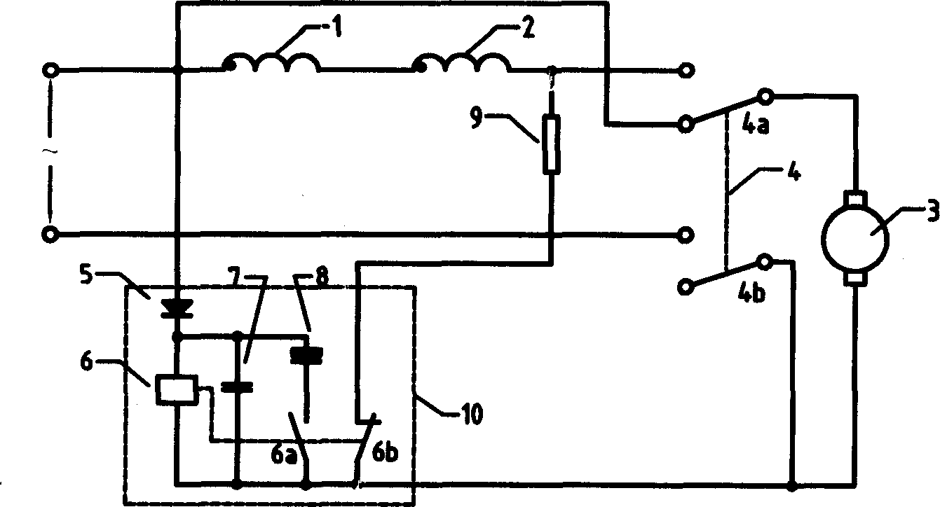
[0015] like figure 1 As shown, the excitation windings 1 and 2 are connected in series, and the open-circuit reverse connection switch 4 is a double-pole double-throw switch, of which one pole 4b is used as a power switch, and the common terminal of the other pole 4a is connected in series with the armature 3, and the two contacts are respectively connected to the series-connected excitation winding The two ends of 1 and 2 are connected, and the delay control device 10 is composed of diode 5, relay 6, filter capacitor 7, and electrolytic capacitor 8. The diode 5 and relay 6 are connected in series, and the filter capacitor 7, electrolytic capacitor 8 and relay 6 are connected in parallel. When the control device 10 is connected to the power supply, when the power supply is turned on, the normally open contact 6a of the relay 6 is closed, the normally closed contact 6b is disconnected, the power supply charges the electrolytic capacitor 8, and when the power supply is disconnect...


PUM


Abstract

This invention relates to a series excited machine with an electric braking function including an excitation winding and an armature serial to the excitation winding, a power cut-off backing switch, a brake resistor and a delay control device, in which, the power cut-off backing switch cuts off the power to back the two ends of the excitation winding or the armature to be delayed by the delay control device then serial to the braking resistor to form a braking loop with the excitation winding and the armature, which rotates to generate braking current generating brake moment to brake the motor.

Description

technical field [0001] The invention relates to a series-excited motor, in particular to a series-excited motor with electric braking function. Background technique [0002] Series excitation motors are widely used in electric machines such as pruners, chain saws, circular saws, lawn mowers, and grinders. Due to inertia, the working parts of these electric machines still have a long time to move after the power is disconnected. , the movement of the working parts may cause personal injury to the operator or other people. Therefore, it is very necessary to quickly brake the motor and working parts after cutting off the power supply voltage to eliminate potential safety hazards. Therefore, product safety regulations in many countries have clear requirements. [0003] It is a known technology to use a mechanical braking device to brake a series excitation motor, such as a spring friction plate structure, and the resistance of the friction plate makes the motor brake. Obviously...

Claims


Application Information

Patent Timeline
Patent Type & Authority Applications(China)
IPC IPC(8): H02P3/06H02P3/08H02P3/12
Inventor 施祖康孙鹤鸣
Owner 孙鹤鸣
Learn More