Magnetron sputtering planar target material shield cover

A technology of magnetron sputtering and shielding cover, applied in sputtering coating, metal material coating process, ion implantation coating, etc., can solve the problems of waste of resources, high production cost, ignition or short circuit, etc., and achieve The effect of keeping the distance between them stable, reducing the phenomenon of sparking, and reducing the frequency of occurrence

Inactive Publication Date: 2016-10-12
江苏宇天港玻新材料有限公司
View PDF9 Cites 4 Cited by
  • Summary
  • Abstract
  • Description
  • Claims
  • Application Information

AI Technical Summary

Problems solved by technology

[0003] In the application of large-scale planar targets, the traditional shielding cover is a split structure. The four separate baffles around the side of the target are directly fixed on the target back plate by screws, and the non-target areas around the edge of the target surface are fixed on the side. The cover plate mask on the baffle, in the use of large planar targets, the side baffles of this kind of separation structure are too long to be deformed due to heating during the production process, so that the distance between some side plates and the side of the cathode target is too close , more prone to fire or short circuit
[0004] In view of this

Method used


Image

  • Magnetron sputtering planar target material shield cover
  • Magnetron sputtering planar target material shield cover
  • Magnetron sputtering planar target material shield cover

Examples


Example Embodiment

[0029] Embodiment one:

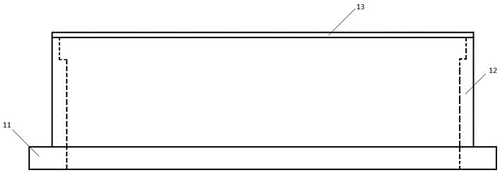
[0030] combined with figure 1 , The magnetron sputtering planar target shielding cover includes a target back plate 11, a shielding cover, surrounding side baffles 12, an upper cover plate 13, and fixing screws. The surrounding side baffles 12 are an integral structure, and the upper cover plate 13 is also an integral structure. The surrounding side baffles 12 are fixed on the target back plate 11 by screws, and a gap is left on the upper side of the surrounding side baffle 12 to ensure that particles and impurities generated during the sputtering process leak through the gaps. The lower edge of the notch is kept at the same height as the upper surface of the cathode target inside the surrounding side baffle 12. After the installation of the surrounding side baffle 12, the distance between it and the side of the internal cathode target should be 0.1-0.5 cm, preferably 0.2 cm. The distance between the side baffle at the upper position and the side of ...

Example Embodiment

[0031] Embodiment two:

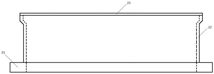
[0032] combined with figure 2 , the magnetron sputtering planar target shielding cover includes a target back plate 21, a shielding cover, surrounding side baffles 22, an upper cover plate 23, and fixing screws. The surrounding side baffles 22 are an integral structure, and the upper cover plate 23 is also an integral structure. The surrounding side baffles 22 are fixed on the target back plate 21 by screws, and a gap is left on the upper side of the surrounding side baffle 22 to ensure that particles and impurities generated during the sputtering process leak through the gaps. The lower edge of the notch is kept at the same height as the upper surface of the cathode target inside the surrounding side baffle 22. After the surrounding side baffle 22 is installed, the distance between it and the side of the internal cathode target should be 0.1-0.5 cm, preferably 0.2 cm. The distance between the side baffle at the upper position and the side of the ca...

Example Embodiment

[0033] Embodiment three:

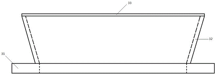
[0034] combined with image 3 , the magnetron sputtering planar target shielding cover includes a target back plate 31, a shielding cover, surrounding side baffles 32, an upper cover plate 33, and fixing screws. The surrounding side baffles 32 are an integral structure, and the upper cover plate 33 is also an integral structure. The surrounding side baffles 32 are fixed on the target back plate 31 by screws, and a gap is left on the upper side of the surrounding side baffles 32 to ensure that particles and impurities generated during the sputtering process leak through the gaps. The lower edge of the notch is kept at the same height as the upper surface of the cathode target inside the surrounding side baffle 32. After the installation of the surrounding side baffle 32, the distance between it and the side of the internal cathode target should be 0.1-0.5 cm, preferably 0.2 cm. The distance between the side baffle at the upper position and the side ...


PUM


Abstract

The invention relates to a magnetron sputtering planar target shielding cover, comprising a target back plate, surrounding side baffles and a cover plate, the cover plate is fixed on the surrounding side baffles, and the surrounding side baffles are fixed on the target back plate , the distance between the upper positions of at least two opposite side guards among the surrounding side guards is greater than the distance between the bottom positions. It can reduce the deformation during the installation and the actual coating heating process, keep the distance between it and the target base stable, and reduce the frequency of sparking caused by the close distance between the cathode and anode.

Description

technical field [0001] The invention relates to the technical field of magnetron sputtering equipment, in particular to a modified magnetron sputtering plane target shielding cover, which is applied to magnetron sputtering thin film deposition. Background technique [0002] In the working process of vacuum magnetron sputtering, the electrons are affected by the electromagnetic field and approach the anode, and their trajectory is a cycloid. During the movement of the electrons to the anode, ionization collisions occur with Ar atoms, and the generated Ar ions are under the force of the electric field. Accelerated to fly to the cathode target under the action of high energy, and bombard the target with high energy, resulting in sputtering effect. In order to ensure the purity of the deposited film during the magnetron sputtering process, it is necessary to add a shield around the side of the planar target and the non-target area of ​​the target surface, where the radius of the...

Claims


Application Information

Patent Timeline
IPC IPC(8): C23C14/35
CPCC23C14/35C23C14/3407
Inventor 王进东
Owner 江苏宇天港玻新材料有限公司
Why Eureka
Try Eureka