Coupling interface and method of operation

An interface and electrical coupling technology, applied in the direction of coupling devices, components of connecting devices, connections, etc., can solve problems such as short circuits that cannot be excluded, and achieve the effect of reducing the risk of sparks or overheating, avoiding short circuits, and reducing energy consumption

Pending Publication Date: 2020-02-14
ENERGYSQUARE
View PDF9 Cites 3 Cited by
  • Summary
  • Abstract
  • Description
  • Claims
  • Application Information

AI Technical Summary

Problems solved by technology

[0014] These methods are not entirely satisfactory as they represent constraints on the layout of the charging surface and / or the contacts of the charging terminals of the device and do not exclude inadvertently caused short circuits
Additionally, prior art approaches tend to require complex electronics in the devices themselves in order for the devices to be efficiently detected and differentiated

Method used


Image

  • Coupling interface and method of operation
  • Coupling interface and method of operation
  • Coupling interface and method of operation

Examples


Embodiment Construction

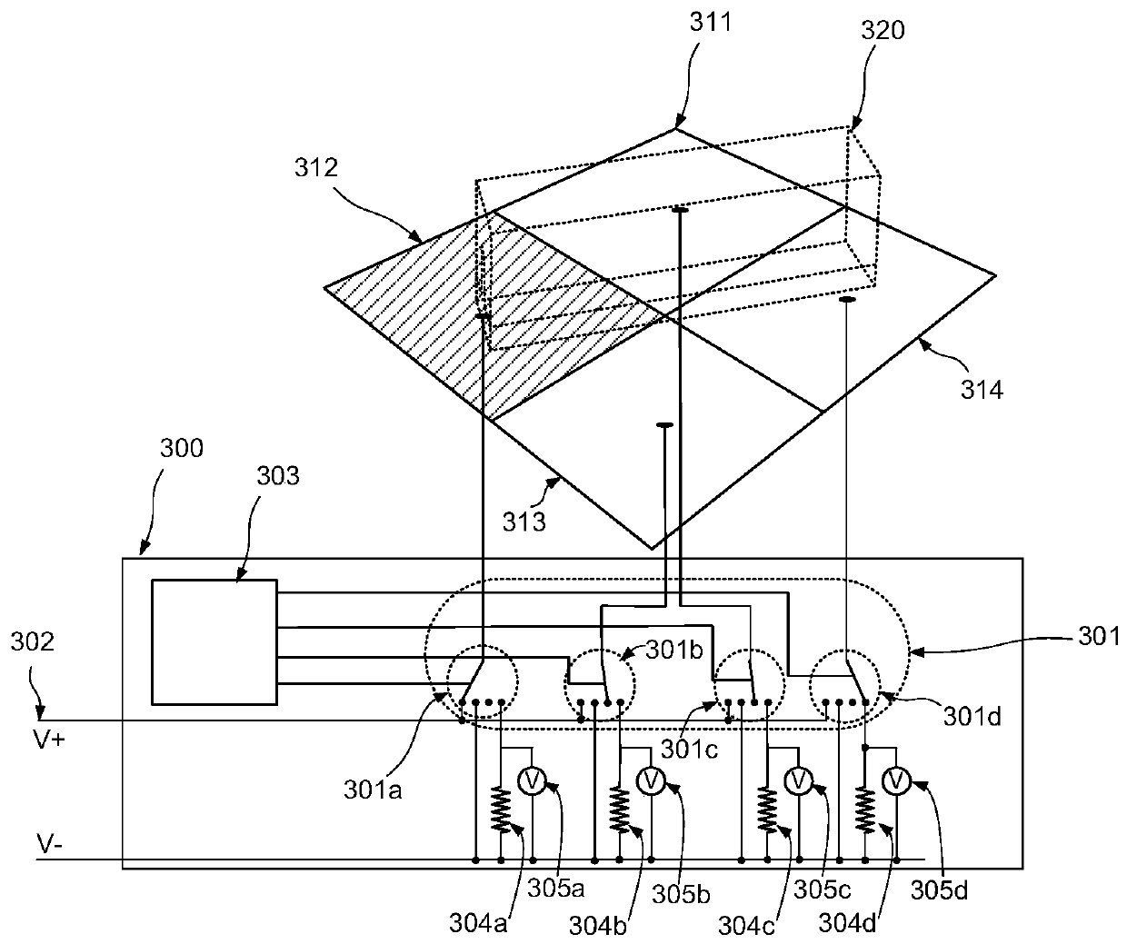
[0061] image 3 A first embodiment of the described solution is shown.

[0062] Such as image 3 As shown in , a coupling interface 300 for establishing an electrical connection with a conductive object 320 is provided.

[0063] The coupling interface 300 controls a plurality of conductive areas 311, 312, 313, 314 constituting the mating surface, each conductive area 311, 312, 313, 314 being switchably coupled under the control of the coupling interface 300, for example by means of an electronically controlled switch 301 to a first voltage, shown here by way of example as the supply voltage V+ on the supply line 302 . Additional supply voltage rails and corresponding switch positions may be provided, as discussed below. The supply voltage may be any convenient voltage, eg 3.3V, 5V, 12V, 20V, etc. The supply voltage may be a DC voltage or an AC voltage. As described herein, the voltage used for the testing process need not correspond to the supply voltage required by the d...


PUM


Abstract

A charging surface comprising multiple conductive regions can be used to charge an electronic device placed on it the surface so that electrodes on the device engage respective conductive regions of the surface. In order to distinguish such chargeable devices from short circuits and other spurious connections, the coupling interface associated with the charging surface is controlled so as to establish a text voltage across each pair of conductive regions in sequence, and look for pairs of conductive region demonstrating a voltage drop characteristic of a particular class of device. Relationships between every pair of conductive regions can be determined and recording, and the voltage level supplied to each conductive region set accordingly. The coupling interface may furthermore operate toidentify device classes, and to set supply voltages or establish additional connections on the basis of stored device class information. Discrimination on the basis of voltage drop can be enhanced bythe provision of a coupling adapted associated with a device to be detected, where the coupling adapter demonstrates an anti-inversion characteristic, for example implemented with a MOSFET, across atleast a pair of these electrodes.

Description

technical field [0001] The present invention relates generally to establishing electrical connections in the context of supporting arbitrary device setups, and in particular in planar recharging surfaces with multiple contact areas. Background technique [0002] Portable electronic devices have become increasingly common in recent years - phones, media players, tablet and laptop computers, IoT (Internet of Things) devices and more, as well as portable speaker units are now widely distributed. With the trend towards miniaturization on the one hand, and with the ever-increasing size and brightness of displays and the desire for wireless connectivity on the other hand, the demands on the energy storage capacity of the batteries of these devices are increasingly demanding. challenge. Given these considerations, users are increasingly experiencing "low battery anxiety," where the charge levels of their various devices and the time until the next opportunity to recharge the vario...

Claims


Application Information

Patent Timeline
Patent Type & Authority Applications(China)
IPC IPC(8): H02J7/00G01R19/00H01R25/00H05K1/11
CPCH02J7/0042H01R13/70H02J7/00036H02J2207/20H02J7/00047H02J7/0013H02J7/0045
Inventor D·洛洛T·勒凯纳M·普瓦达
Owner ENERGYSQUARE
Why Eureka
Try Eureka