Coolant heating structure using infrared ray heating for image display

A technology of image display equipment and heating structure, which is applied in lighting and heating equipment, image communication, cooling/ventilation/heating transformation, etc., can solve the problems of long warm-up time, economic loss, etc., and achieve shortened length, reduced production equipment, The effect of shortening the work period

Inactive Publication Date: 2006-08-30
LEIJIN ELECTRONIC SHENYANG CO LTD
View PDF0 Cites 0 Cited by
  • Summary
  • Abstract
  • Description
  • Claims
  • Application Information

AI Technical Summary

Problems solved by technology

[0014] However, the heat conduction method of the above-mentioned traditional technology is to heat the coolant completely by the heat generated by the picture tube, that is, the heat generated by the electron beam emitted by the electron gun hitting the phosphor. Therefore, in order to heat the coolant The problem that it takes a long time to warm up the mirror meter to stabilize the focal length of the screen
[0015] Along with the extension of heat conduction time, longer warm-up time and extended work period are required on the production line, resulting in economic losses. Therefore, there is an urgent need for a picture tube assembly structure of a picture tube rear-projection TV set that shortens the heat conduction time to the greatest extent.

Method used


Image

  • Coolant heating structure using infrared ray heating for image display
  • Coolant heating structure using infrared ray heating for image display
  • Coolant heating structure using infrared ray heating for image display

Examples


Embodiment Construction

[0039] Hereinafter, embodiments of the present invention will be described in detail with reference to the accompanying drawings.

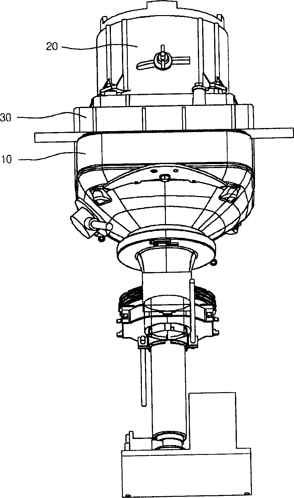
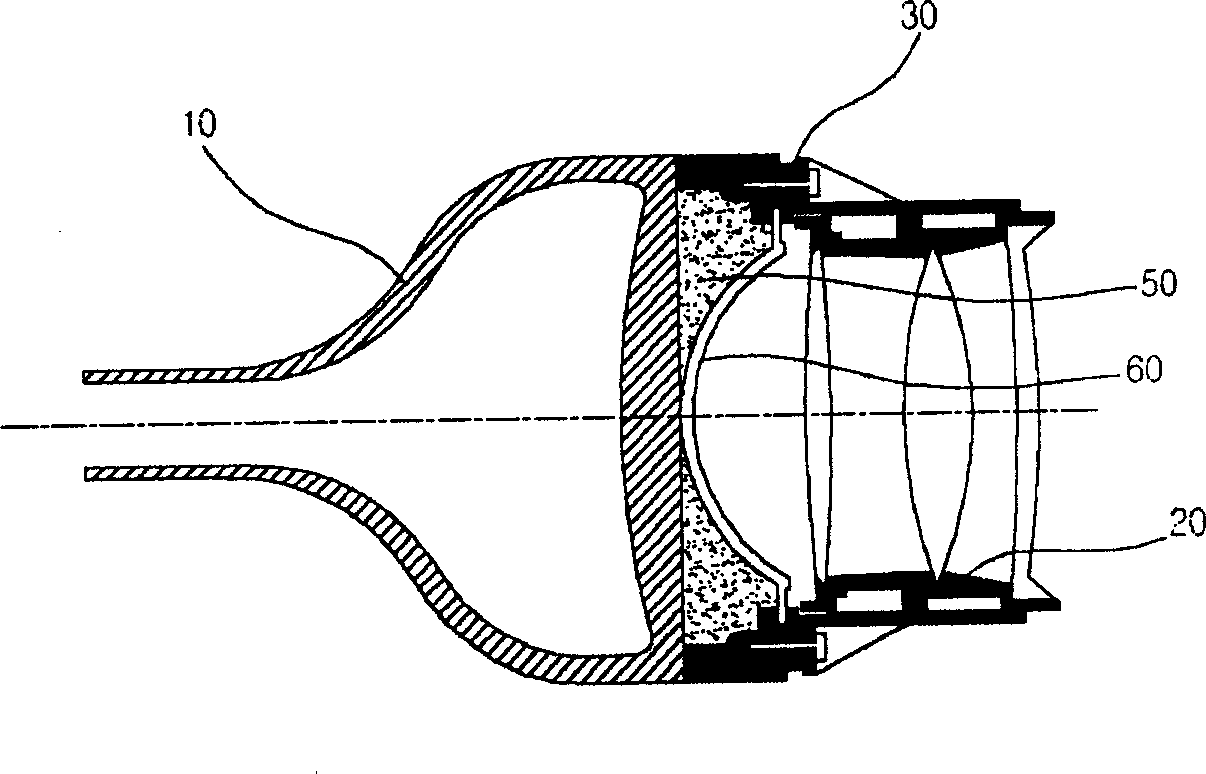
[0040] Figure 4 It is an implementation example of the present invention, a schematic diagram of the exploded structure of the coolant heating structure of the image display device utilizing the infrared heating device, as seen on the same drawing, the picture tube assembly structure of the embodiment of the present invention is, Picture tube 110; the projection mirror device 120 that the image emitted by the picture tube 110 is enlarged and projected at a certain magnification; the connector 130 for mechanically connecting the above-mentioned picture tube 110 and the projection mirror device 120; injecting the above-mentioned connector 130 / projection mirror device 120 / picture tube 110 Combined internal space, composed of exothermic coolant.

[0041] At this time, the above-mentioned coolant not only minimizes the reflected light generated betwe...


PUM


Abstract

This invention relates to an image display equipment composed of a picture display device, a projecting mirror, a connector mechanically connecting the two devices and a coolant injected into the combined internal space of said three devices characterizing in covering an infrared heating device on the top of said image device connector to generate infrared to pre-heat the coolant inside of the connector along with introducing supply to the heating device in order to reduce the pre-heat time on the production line of producing image display devices.

Description

[0001] Field [0002] The present invention relates to a kind of image display equipment, especially a kind of in order to shorten the thermal conduction time of the picture tube assembly that has great influence on the focal length of the picture picture like the picture tube rear projection TV set, utilize the additional infrared heating device to heat the inside of the connector The coolant heating image shows the coolant heating structure of the device. Background technique [0003] Generally speaking, it is impossible to commercialize TVs equipped with picture tubes larger than 36 inches. Therefore, the screens of general TVs are developed by using mirrors and optical mirrors to project on the screen. Rear projection is used. TV set. [0004] According to the driving components of such rear-projection TVs, TVs are divided into CRT rear-projection TVs, LCD rear-projection TVs, digital rear-projection TVs, etc., but their structures are usually very similar. [0005] fig...

Claims


Application Information

Patent Timeline
Patent Type & Authority Applications(China)
IPC IPC(8): H05K7/20F25B27/00G09F9/30H04N5/64H04N5/74
Inventor 李炅昊
Owner LEIJIN ELECTRONIC SHENYANG CO LTD
Why Eureka
Try Eureka