
Image forming apparatus

A technology of inkjet recording, equipment, applied in printing etc., which can solve problems such as difficulty in uniformity of distance, degradation of image quality, etc., and achieve effects of preventing deterioration, uniformity of shape and position, and improvement of user-friendly functions

Inactive Publication Date: 2006-09-06
BROTHER KOGYO KK
View PDF1 Cites 0 Cited by
  • Summary
  • Abstract
  • Description
  • Claims
  • Application Information

AI Technical Summary

Problems solved by technology

[0007] However, when the recording head and the ink cartridge are arranged in the relationship described above, the distance between each pair of them will hardly be uniform.
Therefore, the length of the ink tube will vary, causing a decrease in image quality

Method used


Image

  • Image forming apparatus
  • Image forming apparatus
  • Image forming apparatus

Examples


Embodiment Construction

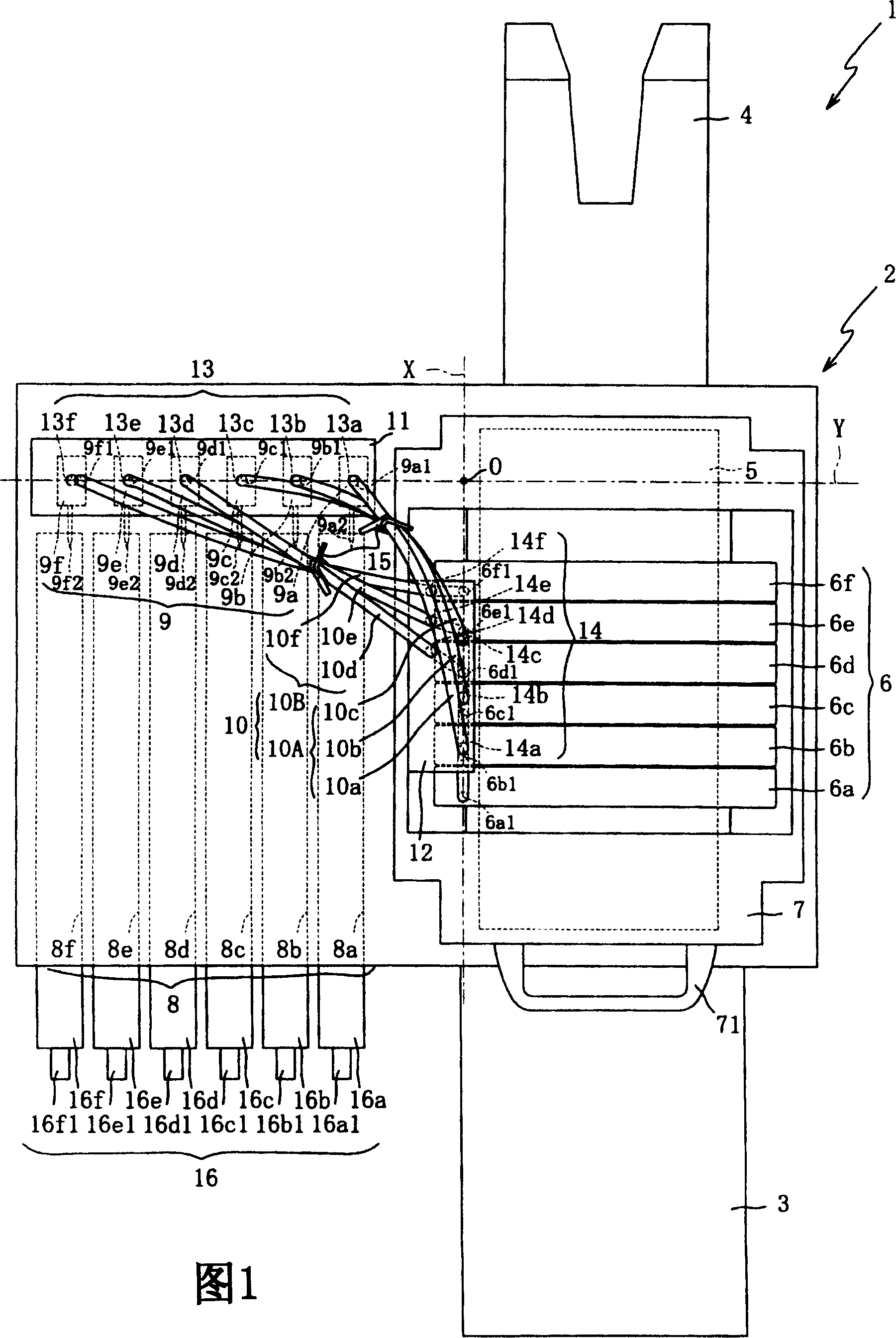
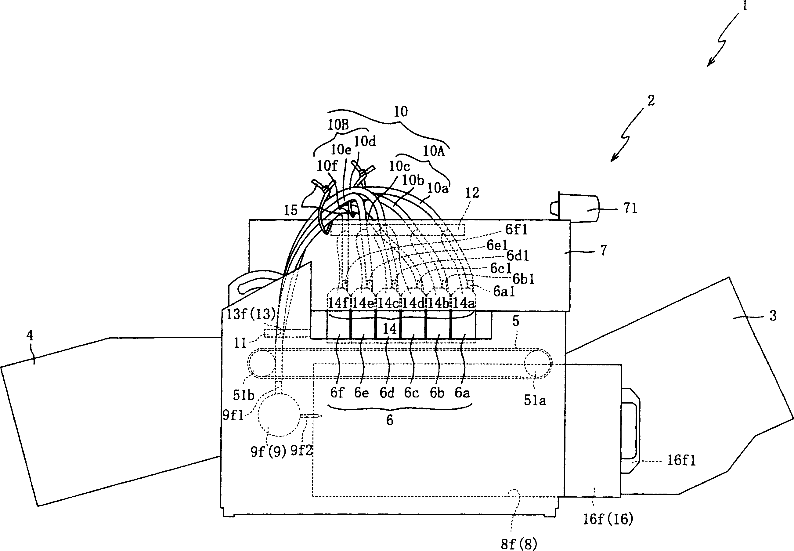
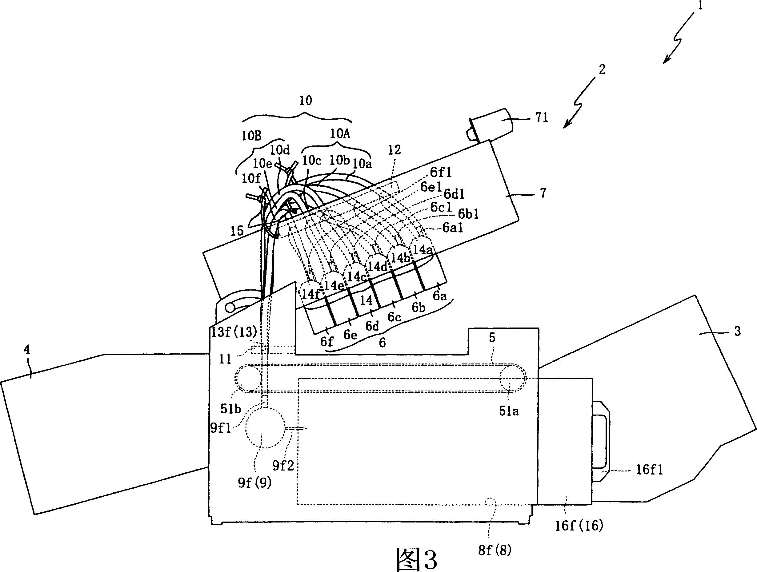
[0043] Preferred embodiments of the present invention are described below with reference to the accompanying drawings. Fig. 1 is a top view of an inkjet recording apparatus 1 according to a first embodiment of the present invention. The description will start with the general arrangement of the inkjet recording apparatus 1 with reference to FIG. 1 .

[0044] The inkjet recording apparatus 1 includes: a supply unit 3 (recording medium supply unit) for supplying a recording medium (not shown); forming an image; and a stacker 4 for storing recording media on which an image is formed by the main body 2 .

[0045] The supply unit 3 includes a tray (not shown) for accommodating a recording medium and a pickup roller (not shown) for contacting the recording medium accommodated in the tray. The supply unit 3 is designed for supplying recording media to the main body 2 when the pickup roller is actuated. A new recording medium is loaded into the supply unit 3 from the front side or ...


PUM


Abstract

An ink jet recording apparatus (1) is arranged in which the loading and unloading of ink cartridges (16) as well as the supply and removal of a recording medium is carried out at the upstream side in a conveying direction. The ink tubes (10) for connecting ink dispensing outlets (9a1 to 9f1) and ink dispensing inlets (6a1 to 6f1) are positioned so that they are substantially uniform in the length thus to have no difference in the resistance to flows.

Description

technical field [0001] The present invention relates to an inkjet recording apparatus, and more particularly, to an inkjet recording apparatus capable of improving user-friendly functions while avoiding deterioration of image quality. Background technique [0002] Inkjet recording apparatuses for ejecting ink onto a recording medium to form a desired image are roughly classified into two types: serial type inkjet recording apparatuses equipped with components arranged to be movable in one direction a recording head; and a line inkjet recording apparatus equipped with a fixed recording head. [0003] In Japanese Laid-Open Patent Application No. 2002-240316, there is disclosed a serial type inkjet recording apparatus in which an inkjet (recording) head thereof is supplied with ink from an ink cartridge through a flexible ink tube. This makes it easy for the ink tube to bend when the inkjet head moves. [0004] However, since the ink tubes of the conventional serial inkjet re...

Claims


Application Information

Patent Timeline
IPC IPC(8): B41J2/175B41J2/18B41J2/01
CPCB41J2/17523
Inventor 高木修
Owner BROTHER KOGYO KK
Learn More