Method and device for estimating charge/discharge electricity amount of secondary cell

A technology for discharging electricity and secondary batteries, which is applied in measuring devices, measuring electrical variables, measuring electricity, etc., can solve problems such as poor working conditions, low accuracy, and rising costs, and achieve long-life protection and control, improve Effects of Estimation Accuracy

Active Publication Date: 2006-09-06
PANASONIC EV ENERGY CO LTD
View PDF1 Cites 15 Cited by
  • Summary
  • Abstract
  • Description
  • Claims
  • Application Information

AI Technical Summary

Problems solved by technology

When this current sensor is used in HEV, etc., it is necessary to measure a large current, and the cost increases when a high-precision current sensor is used, so the actual situation is that a low-cost and low-precision current sensor has to be used.
Therefore, a measurement error is included in the current value detected by the current sensor, and this current error becomes an estimation error of SOC
Especially when the charge-discharge rate is smaller than the current error (for example, for a charge-discharge rate of 1A, there is a current error of ±2A, etc.), the operating conditions of the estimated SOC change signifi

Method used


Image

  • Method and device for estimating charge/discharge electricity amount of secondary cell
  • Method and device for estimating charge/discharge electricity amount of secondary cell
  • Method and device for estimating charge/discharge electricity amount of secondary cell

Examples


Example

[0042] (First embodiment)

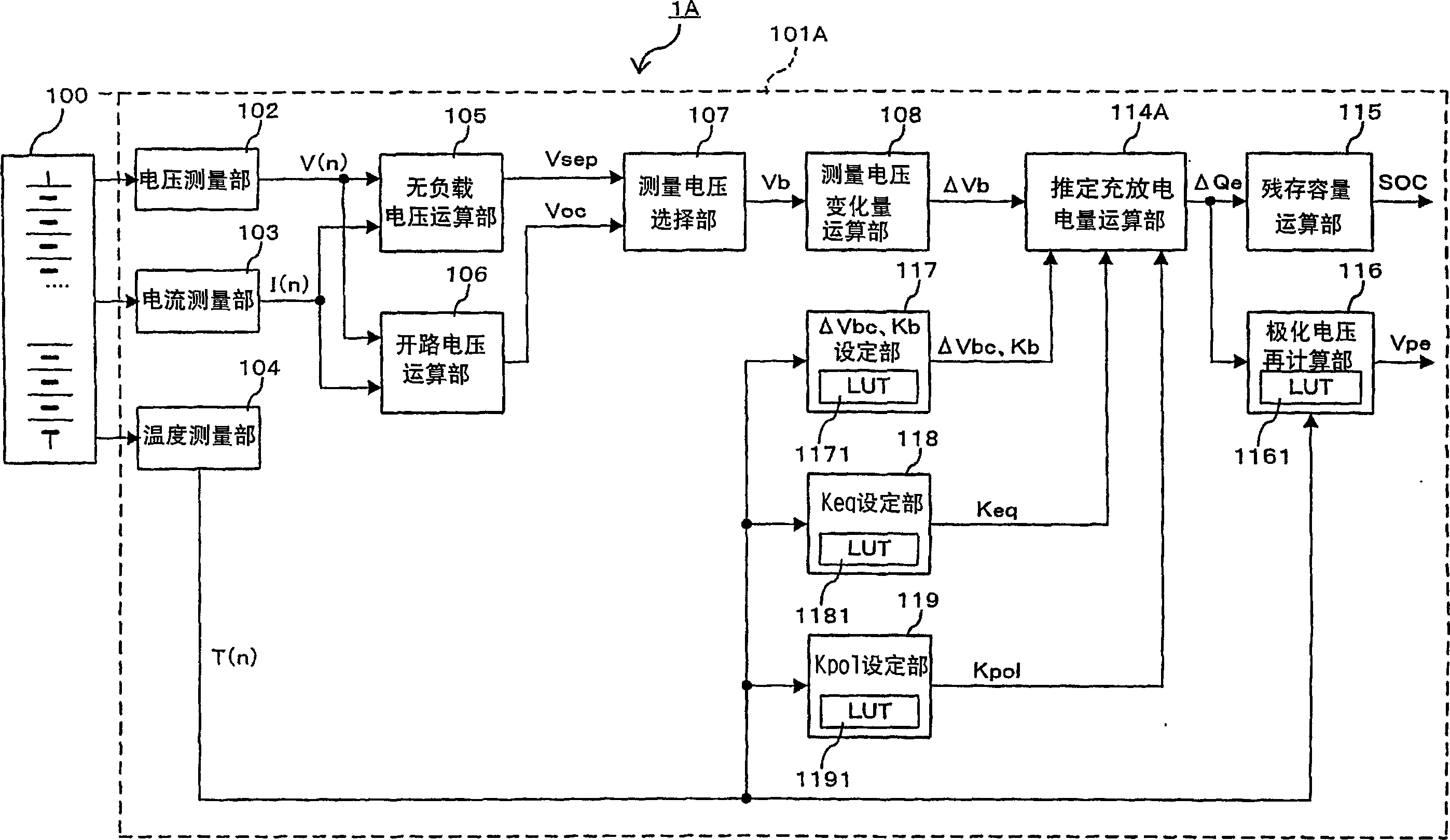
[0043] figure 1 It is a block diagram showing a configuration example of the battery pack system of the first embodiment of the present invention. in figure 1 Here, the battery pack system 1A includes a battery pack 100 and a battery ECU 101A including the remaining capacity estimation device of the present invention as a part of the microcomputer system.

[0044] When the battery pack 100 is mounted on an HEV or the like, it is usually in order to obtain a predetermined output to the motor. For example, a battery block in which a plurality of single cells or unit cells of a nickel-hydrogen battery are electrically connected in series is further connected in series. constitute.

[0045] In the battery ECU 101A, 102 is a voltage measuring unit that measures the terminal voltage of each battery block in the battery pack 100 detected by a voltage sensor (not shown) as voltage data V(n) in a predetermined sampling period. 103 is a current measuring unit ...

Example

[0069] (Second embodiment)

[0070] Figure 4 It is a block diagram showing a configuration example of the battery pack system according to the second embodiment of the present invention. Again, in Figure 4 In the description of the first embodiment. figure 1 The parts with the same structure and function are assigned the same reference numerals and the description is omitted.

[0071] The current data I(n) measured by the current measurement unit 103 is input to the measured charge and discharge power calculation unit 109. The measured charge and discharge power calculation unit 109 calculates the measured charge and discharge power ΔQm in a predetermined period (for example, one minute) based on the current data I(n) in the charging direction and the discharge direction.

[0072] Next, the measured charge and discharge power amount ΔQm from the measured charge and discharge power calculation unit 109 is input to the polarization voltage calculation unit 110. The polarization ...


PUM


Abstract

When a particular selection condition is satisfied, a no-load voltage calculation section (105) calculates a no-load voltage Vsep which is a voltage piece when the current in the approximate straight line obtained by statistical processing is zero for a plurality of set data consisting of current data I(n) and voltage data V(n). Moreover, when a particular current condition is satisfied continuously for a certain time, a release voltage calculation section (106) calculates the terminal voltage of the secondary cell as a release voltage Voc. By using a preset voltage change amount adjustment constant DeltaVbc, an adjustment coefficient Kb, an electromotive force change constant Keq, and a polarization voltage generation constant Kpol, an estimated charge/discharge electricity amount calculation section (114) calculates an estimated charge/discharge electricity amount DeltaQe as a function of a no-load voltage in a predetermined period or a release voltage change amount DeltaVb.

Description

technical field [0001] The present invention relates to estimating the residual battery life of a secondary battery such as a nickel-hydrogen (Ni-MH) battery mounted as a power source of a motor or a driving source of various loads in an electric vehicle (PEV) or a hybrid vehicle (HEV). Capacity (SOC: State of Charge) technology. Background technique [0002] Conventionally, in HEVs, the voltage, current, temperature, etc. of the secondary battery are detected, and the remaining capacity of the secondary battery (hereinafter, abbreviated as SOC) is estimated by calculation, and the SOC control is performed to optimize the fuel consumption efficiency of the vehicle. it is good. In order to accurately control the SOC, it is necessary to accurately estimate the SOC of the secondary battery being charged and discharged. [0003] As such a conventional SOC estimation method, there is the following method: First, measure the battery voltage V and the charged and discharged curre...

Claims


Application Information

Patent Timeline
IPC IPC(8): G01R31/36
Inventor 村上雄才山边律人
Owner PANASONIC EV ENERGY CO LTD
Why Eureka
Try Eureka