Multi-chip high power LED device

A light-emitting diode, high-power technology, applied in the field of semiconductors, can solve problems such as affecting luminous performance, current imbalance in parallel circuits, large thermal effects, etc., and achieve good heat dissipation performance, high luminous intensity, and low cost.

Inactive Publication Date: 2006-09-13
SOUTH CHINA NORMAL UNIVERSITY
View PDF0 Cites 6 Cited by
  • Summary
  • Abstract
  • Description
  • Claims
  • Application Information

AI Technical Summary

Problems solved by technology

The current disadvantages of high-power light-emitting diodes are: (1) only a few companies can manufacture single-chip power devices, and the sales cost is tens to hundreds of times higher, and this product is not conducive to mass use; (2) single-chip power devices The power supply current of the power device is large, so the thermal effect is large, which seriously affects the luminous performance; (3) the technology is not very mature, which is not conducive to a large number of promotion and application; (4) the existing multi-chip light-emitting diode device has no temperature compensation, each parallel circuit Unbalanced current, easily affected by temperature changes, and even lead to chip damage

Method used


Image

  • Multi-chip high power LED device
  • Multi-chip high power LED device
  • Multi-chip high power LED device

Examples


Embodiment Construction

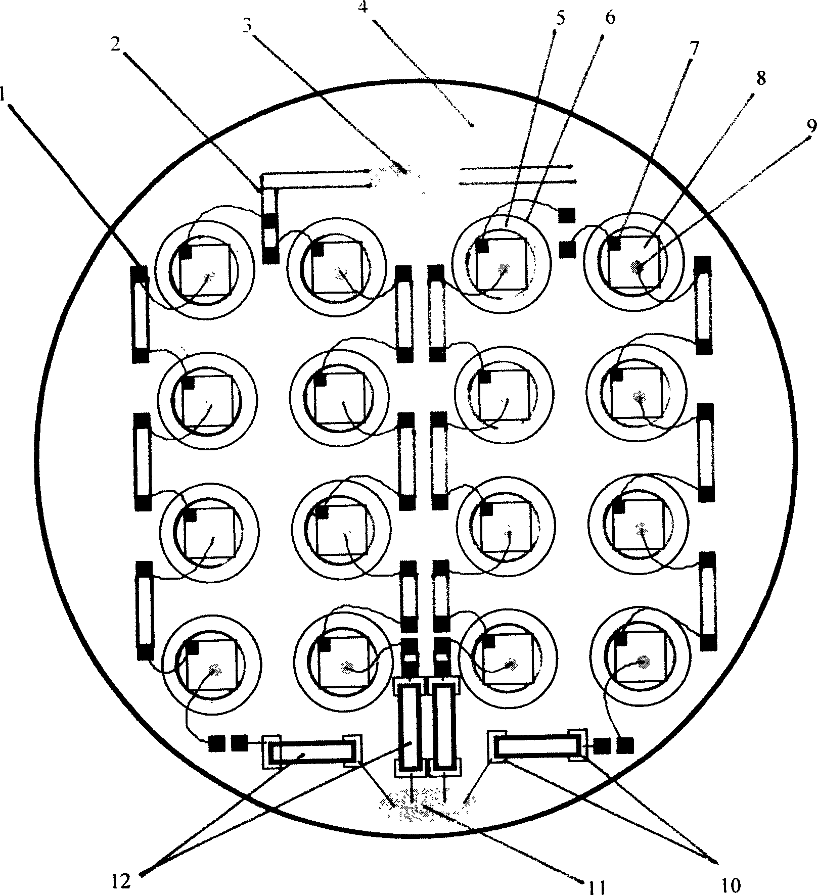
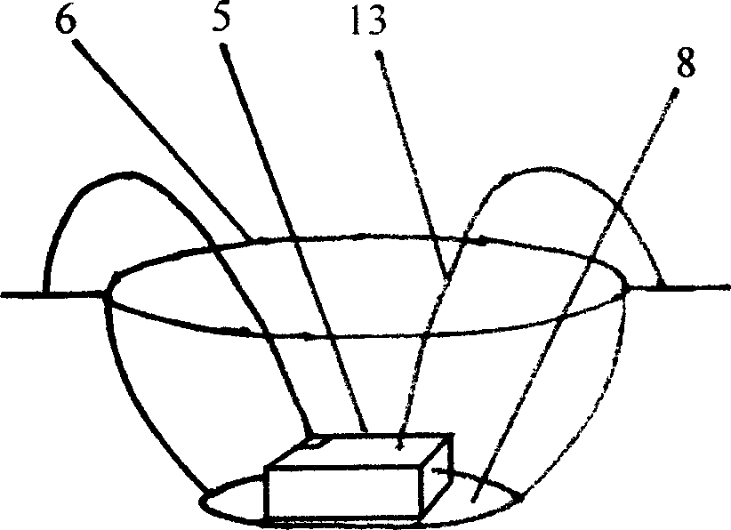
[0013] Such as figure 1 , 2 As shown, a metal substrate is used, and the cup-shaped groove 6 for installing the chip 8 is processed on the metal substrate 4, so that an LED chip 8 is installed in each cup-shaped groove 6;

[0014] Add flexible electrode plates 1 and 2 on the plane of the substrate, and the chip electrodes installed in the cup-shaped grooves are welded to the flexible electrode plates through gold wires, and the chips of a series circuit are connected in series;

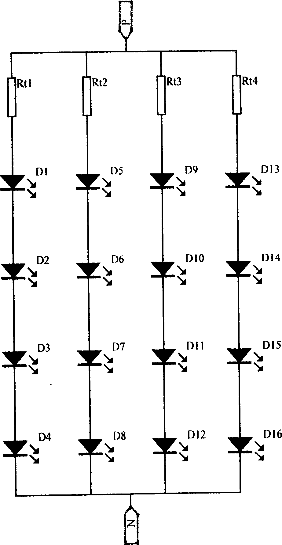
[0015] Multiple light-emitting diodes in each single group are connected in series, and then connected in series with a thermistor 12 to form a series circuit composed of light-emitting diodes and thermistors, and each series circuit is connected in parallel with each other.

[0016] The circuit formed is as image 3 As shown, it consists of 4 sets of series circuits, the resistance Rt 1 ~Rt 4 is the thermistor, D 1 ~D 16 is the LED, the thermistor Rt 1 , LED D 1 ~D 4 Form the first series ci...


PUM


Abstract

This invention relates to a multi-chip large power LED component, which is processed by making cup-shaped slots corresponding to the numbers of the chips on base boards of metals, ceramics or epoxy resin circuit, encapsulating multiple LED chips in the slots, in which, the chips are serial directly then serial to a thermistor to forma a serial circuit and the serial circuits are parallel to each other, which applies a serial way for single unit and multiple chips and a connection way in parallel, a thermistor is serial to one single unit to maintain equal voltage for the sets, when the temperature of the PN junction of the diode rises or falls, the thermistor changes toward the opposite direction along with the change of the temperature.

Description

technical field [0001] The invention belongs to the technical field of semiconductors, and relates to a multi-chip high-power light-emitting diode device packaged on a metal substrate, a ceramic substrate or an epoxy resin circuit substrate. Background technique [0002] The light-emitting wavelength of a light-emitting diode (LED) changes by about 0.2-0.3nm / °C with the change of temperature, and the spectral width also increases accordingly. When the current passes through the pn junction, the temperature of the junction area will rise, and the luminous intensity will decrease accordingly by about 1% / 1°C. At present, the method of reducing its driving current is generally used to reduce the junction temperature, and the driving current of most LEDs is limited to about 20mA. However, the light output of LED will increase with the increase of current. At present, the driving current of many power single-chip LEDs can reach 300mA~1A, and its luminous intensity has also increa...

Claims


Application Information

Patent Timeline
Patent Type & Authority Applications(China)
IPC IPC(8): H01L25/16H01L25/00
CPCH01L2224/48091
Inventor 孙慧卿范广涵郭志友
Owner SOUTH CHINA NORMAL UNIVERSITY
Why Eureka
Try Eureka