Dynamic aperture driving apparatus and method for reducing vibration

A driving device, dynamic aperture technology, applied in aperture, projection device, optics, etc., can solve problems such as large instantaneous vibration

Inactive Publication Date: 2006-09-20
SAMSUNG ELECTRO MECHANICS CO LTD
View PDF0 Cites 7 Cited by
  • Summary
  • Abstract
  • Description
  • Claims
  • Application Information

AI Technical Summary

Problems solved by technology

At this moment, the greatest momentary vibrations are generated and the resulting vibrations are converted into noise of the optics, which is the main disadvantage of projection TVs

Method used


Image

  • Dynamic aperture driving apparatus and method for reducing vibration
  • Dynamic aperture driving apparatus and method for reducing vibration
  • Dynamic aperture driving apparatus and method for reducing vibration

Examples


Embodiment approach

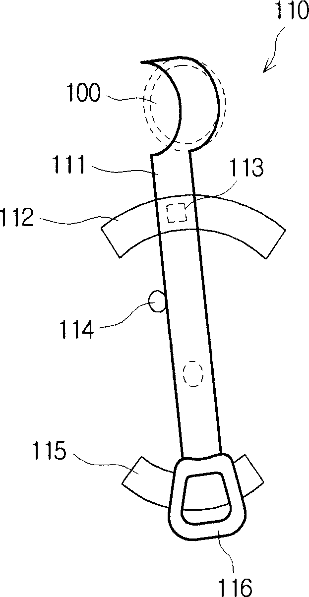
[0059] According to one embodiment, the detection device comprises a sensor magnet 112 and a Hall sensor. The sensor magnet 112 is placed parallel to the rotation path of the rotating device and varies linearly along the length of the sensor magnet so as to provide a different magnetic field strength according to each rotation angle of the rotating device. The hall sensor is integrally rotated with the rotating device, and converts the magnetic field strength of the sensor magnet 112 which changes according to the rotating angle of the rotating device into an electric signal.

[0060] According to another embodiment, the detection device comprises a sensor magnet (not shown) and a Hall sensor. The sensor magnet is placed at a predetermined position so that the gap between the rotating device and the predetermined position changes with the rotation of the rotating device, and has a constant magnetic field strength. The Hall sensor is integrally rotated with the rotating device...


PUM


Abstract

The present invention generally relates to a dynamic aperture for controlling the intensity of light of projection lens, more particularly to a dynamic aperture driving apparatus and method for reducing vibration by which vibrations are minimized in spite of command for sudden location change. The dynamic aperture driving apparatus comprises rotating means, driving means, sensing means and driving control means, whereas a location control signal is characterized by minimizing vibration when the rotating means arrives at a commanded location by an increase in rising time and / or falling time of a target location signal through an RC integral circuit within the driving control means.

Description

technical field [0001] The present invention generally relates to a dynamic aperture for controlling the light intensity of a projection lens, and more particularly to a dynamic aperture driving device and method for reducing vibration, thereby reducing vibration even under command of a sudden change in position to a minimum. Background technique [0002] Recently, projection TVs and projectors have become popular as a high-definition large-screen display device. Projection TVs and projectors work on the principle of optics, figure 1 The optical structure of these types of projection TVs and projectors is shown. [0003] see figure 1 , the projection device includes an illumination optical system 1a, a reflective display element 1b and a projection optical system 1c. [0004] The illumination optical system 1a is a light-emitting part, and includes: a lamp (not shown) that emits light; a light source 10 that has a mirror for reflecting emitted light and guiding a light p...

Claims


Application Information

Patent Timeline
Patent Type & Authority Applications(China)
IPC IPC(8): G03B7/00G03B9/07H04N5/225G03B21/00G03B21/14
CPCG03B21/14H04N5/74
Inventor 李七星
Owner SAMSUNG ELECTRO MECHANICS CO LTD
Why Eureka
Try Eureka