Slag-back prevention and parallel aeration process for blast furnace

A blast furnace and air supply technology, which is applied to blast furnaces, blast furnace details, blast furnace parts, etc., can solve problems such as insufficient performance of the air supply system, unbalanced equipment configuration, and slag filling of blast furnaces to avoid economic losses, The effect of improving the utilization factor and increasing the iron output

Inactive Publication Date: 2006-09-27
燕永存
View PDF0 Cites 10 Cited by
  • Summary
  • Abstract
  • Description
  • Claims
  • Application Information

AI Technical Summary

Problems solved by technology

[0003] In order to solve the unbalanced equipment configuration of the existing blast furnace air supply system, the insufficient performance of the air supply system, and the problems of blast furnace shutdown and blast furnace slag filling caused by the failure of the air supply system, the invention provides a blast furnace air supply system Parallel air supply technology, which can not only avoid blast furnace shutdown and blast furnace slag filling caused by air supply equipment, but also increase blast furnace air supply volume to varying degrees according to different process conditions, improve blast furnace utilization factor and blast furnace Yield

Method used


Image

  • Slag-back prevention and parallel aeration process for blast furnace
  • Slag-back prevention and parallel aeration process for blast furnace
  • Slag-back prevention and parallel aeration process for blast furnace

Examples


Embodiment 1

[0023] Example 1: One fan provides parallel auxiliary wind or security wind process for multiple blast furnaces

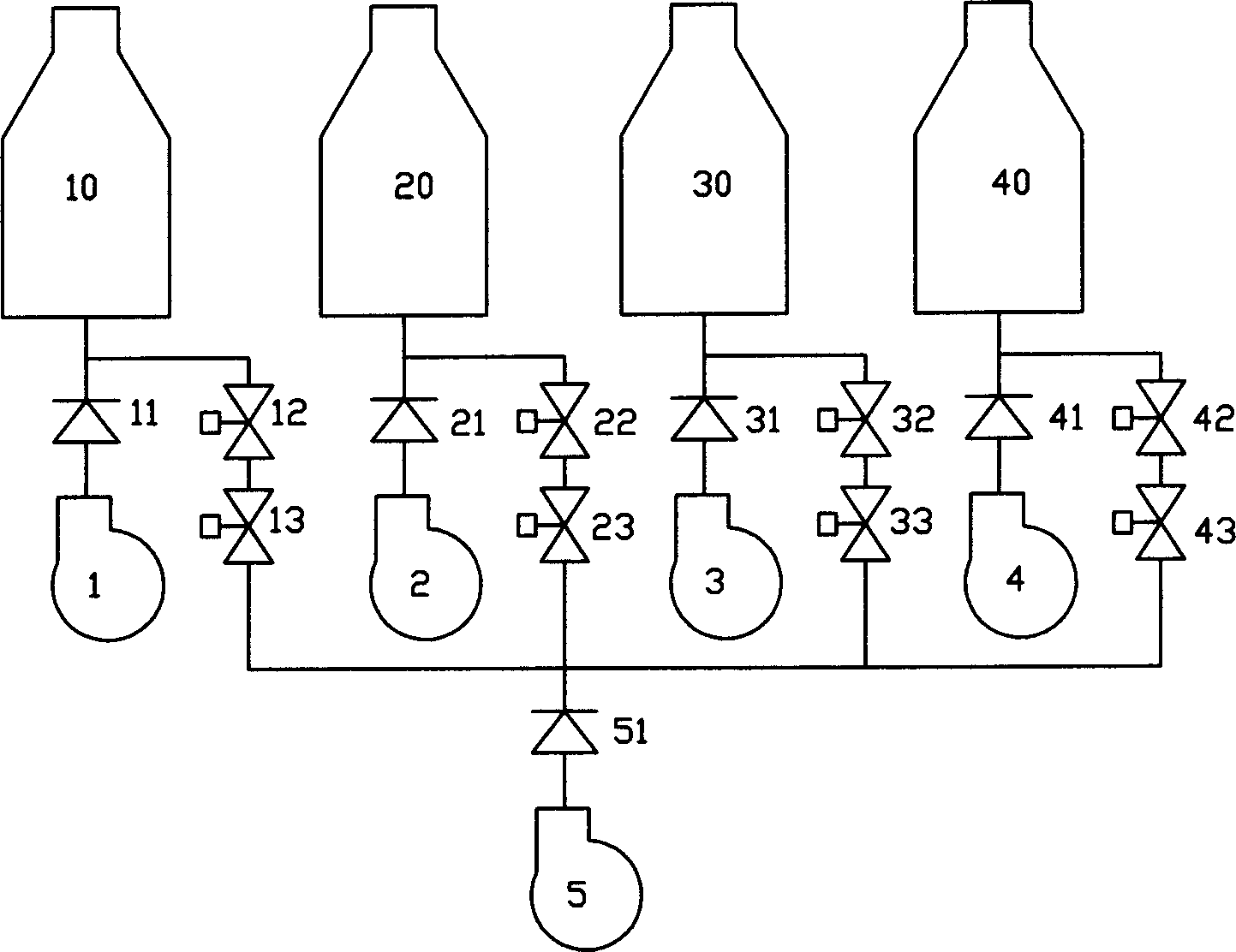
[0024] Such as figure 1 As shown, the relationship between blast furnace and fan configuration is shown in Table 1. No. 1 fan 1, No. 2 fan 2, No. 3 fan 3, and No. 4 fan 4 are all single main supply fans, respectively No. 1 blast furnace 10 and No. 20. The main air supply for No. 3 blast furnace 30 and No. 4 blast furnace 40, and No. 5 blower fan 5 is a parallel auxiliary supply fan, which can provide auxiliary wind or security wind for some or all blast furnaces in No. 1 to No. 4 blast furnaces at the same time.

[0025] Table 1. Possible configuration relationship between blast furnace and fan

[0026]

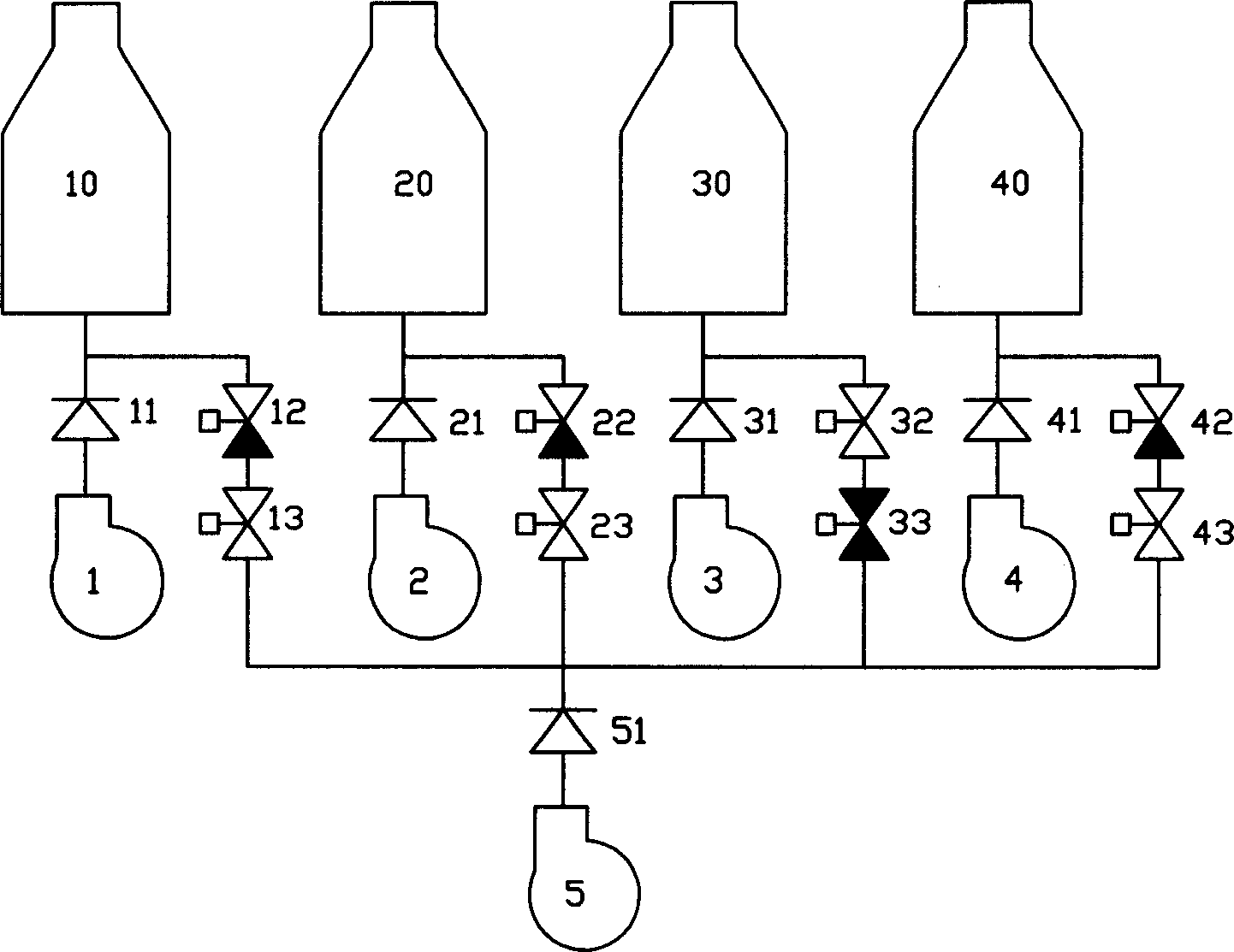
[0027] Such as figure 2 As shown, the No. 1 fan 1, the No. 2 fan 2, the No. 3 fan 3 and the No. 4 fan 4 respectively pass through the check valve 11, the check valve 21, the check valve 31, and the check valve 41 to the No. 1 blast furnace 10 a...

Embodiment 2

[0030] Embodiment 2 A blower is used as the main blower and at the same time, the excess wind is used to provide parallel auxiliary wind or security wind for multiple blast furnaces.

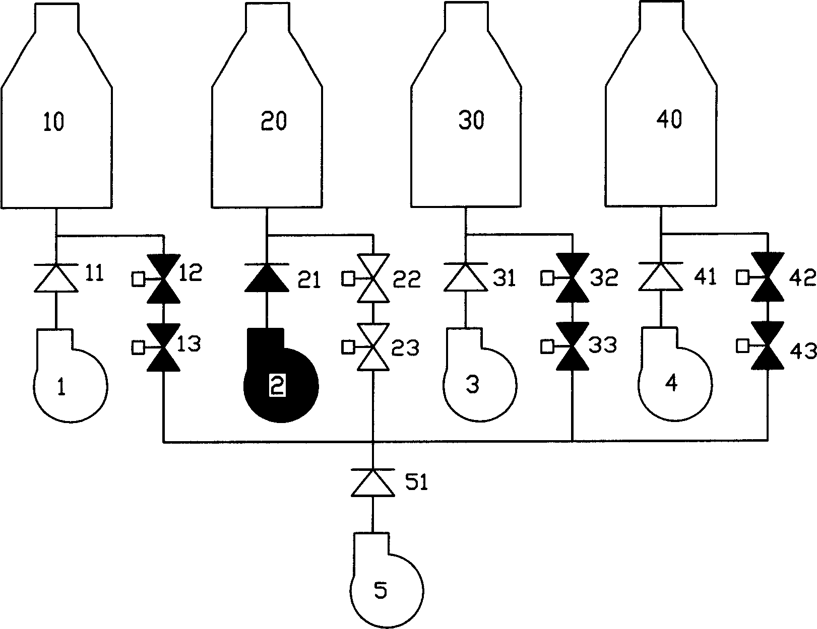
[0031] Such as Figure 5As shown, No. 1 fan 1, No. 2 fan 2, No. 3 fan 3, and No. 4 fan 4 are single main supply fans, which are respectively the No. 1 blast furnace 10, No. 2 blast furnace 20, No. 3 blast furnace 30, and No. 4 blast furnace 40. Main air supply, No. two blower fan 2 is except being No. two blast furnace 20 main air supply, and its excess wind can provide auxiliary wind or security wind for part or all blast furnaces in other three blast furnaces simultaneously.

[0032] Table 2. Possible configuration relationship between blast furnace and fan

[0033]

[0034] Such as Image 6 As shown, in the present invention, the No. 2 fan 2 provides auxiliary air for the No. 1 blast furnace 10 and provides security air for the No. 3 blast furnace 30 while providing the ...


PUM


Abstract

This invention provides the residue-proof and parallel connection air feed process of the high furnace, it can solve such problems as the disbalanceable hardware configuration in high furnace air feed system, the efficiency of air feed systerm isn't high, and damping down and residue-proof in the high furnace caused by air feed system fault. This invention offers a parallel connection air feed technology in the air feed systerm, installing auxiliary air supply duct on main air supply duct of high furnace fan, install auxiliary one and main one in parallel to form air-supply network, monitor the air supply condition of every high furnace with control system,in order to adjust corresponding parameters, to change-over between main air supply duct and auxiliary one and control them, to make other fans of high furnaces supply air for the high furnace whose air supply is insufficient and the one whose fan is damaged.

Description

technical field [0001] The invention relates to blast furnace air supply equipment, in particular to pipe network configuration and automatic control technology of multiple ironmaking blast furnaces and multiple air supply fans connected in parallel for air supply. Background technique [0002] At present, the known air supply system for ironmaking blast furnaces adopts multiple blower configurations, one for one standby, one for multiple uses and one for multiple standbys, that is, only one blower is in the air supply state for a blast furnace, and the other blowers are used as backup blowers, and The fans of each blast furnace are dedicated fans, which supply air independently and cannot supply air across furnaces. With the development of the enterprise and the transformation of the iron-making process and iron-making equipment, there are often unbalanced equipment matching, insufficient or excessive air supply by the fan, which causes energy waste to the enterprise and af...

Claims


Application Information

Patent Timeline
Patent Type & Authority Applications(China)
IPC IPC(8): C21B9/10
CPCY02P10/20
Inventor 燕永存张建芬马颖李丘生戚振宇王庆河
Owner 燕永存
Why Eureka
Try Eureka